OVERVIEW
This Cisco Validated overview document will aid in configuring Spaces OS, ensuring a robust infrastructure that underpins a Cisco Spaces deployment.
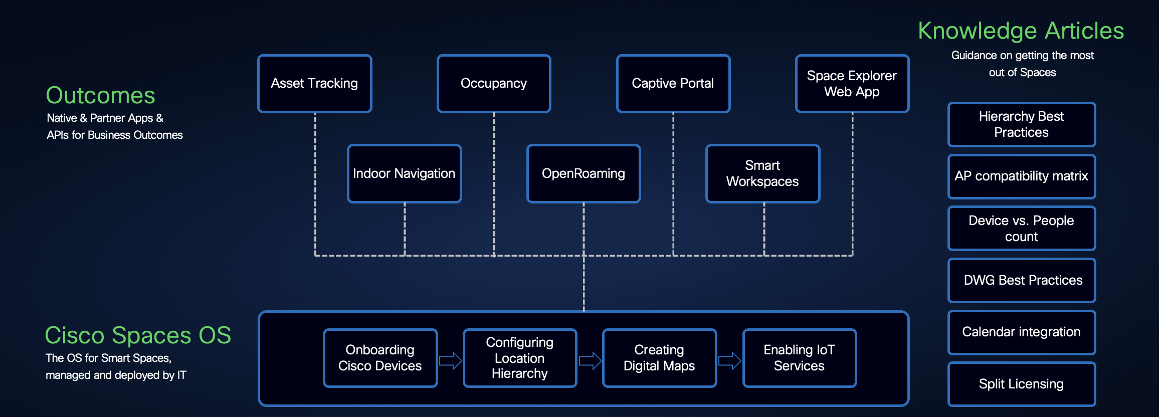
Cisco Spaces OS serves as the foundational layer for deploying and managing intelligent location-based services within an organization. As the essential base installation, Spaces OS integrates a suite of critical components designed to streamline operations and enhance data utilization.
By onboarding data through platforms like Catalyst Center, Wireless LAN Controller (WLC), and Meraki, Spaces OS ensures seamless connectivity and comprehensive data capture. It facilitates the configuration of a unified location hierarchy and merges data from diverse sources to provide a cohesive spatial understanding. Additionally, Spaces OS supports the creation of detailed Digital Maps, offering a visual representation of spaces for better navigation and planning. With the capability to enable IoT streaming services, Spaces OS empowers organizations to leverage real-time data insights for improved decision-making and operational efficiency.
SUPPORT & ONBOARDING INFO
Please follow the link below to find out about the different ways to get support for Cisco Spaces: Support Info Link
SPACES OS INSTALLATION
To complete Spaces OS installation, an admin will require read/write for Cisco Spaces, as well as Catalyst Center, WLC, Meraki Dashboard and Webex Control Hub, or as many as applicable within the environment.
Onboarding Cisco Devices for Intaking Telemetry & Data

Overview
Onboarding data relates to the methods for connecting the telemetry data from the infrastructure to the Spaces dashboard.
Steps below should be completed for as many infrastructure stacks as available - the more data we feed into Spaces, the more valuable the outcomes can become.
Catalyst Wireless
Catalyst Wireless
Spaces Connector
In order to connect the wireless network with Cisco Spaces, Cisco Spaces Connector should be installed on a virtual machine. The Spaces Connector supports VMware ESXi 6.5 or above versions, as well as AWS AMI, Nutanix, and HyperV.
For more Connector VM options and details please review the Connector Configuration page.
The connector supports the Production configuration with the VM requirement as follows:
It is highly recommended that 8 vCPU be used when possible. Using fewer resources is possible but may restrict the ability to run certain services.
Connector Configurations
|
|
Production |
|---|---|
|
vCPU |
8 |
|
Memory (GB) |
16 |
|
Hard Disk (GB) |
120 |
Connector Scaling (Connector v3.3 July 2026 and above only)
|
Connector Type |
Use Case |
AP Count |
Client/Tag Count |
Connector Outgoing Message Rate |
|---|---|---|---|---|
|
Advanced 2 |
Location (NMSP) Only |
25K |
Client Count: 250K (Wireless Clients, RFIDs & Rogues) |
44K NMSP msgs/sec |
|
IoT Only |
4.5K |
BLE Tag Count: 40K |
220K BLE msgs/sec |
|
|
Location (NMSP) + IoT |
18K (3K APs doing both IoT and Location; 15K APs is doing location only) |
Client Count: 150K BLE Tag Count: 30K |
38K NMSP msgs/sec 170K BLE msgs/sec |
For connector scaling please refer to the use cases in the table.
-
Standard configuration provides scaling information for location only per the capacity details provided
-
Running IoT services in addition to location services Cisco Spaces recommends the Production configuration, per the capacity details provided
Connector Scaling and Sizing Best Practices
-
Start with Production and scale down as needed
-
Don’t let CPU and memory go above 75%
-
Adding new services will add additional load
-
Keep an eye on the message rate - add mac prefix filtering as a best practice (can be done via a support case)
Tested VMware Environments
-
VMware ESXi: 6.5.0 Update 2 (Build 13004031), 6.7.0 Update 2 (Build 13006603)
-
VMware vSphere Client Version 6.7.0
-
VMware vCenter Server Appliance 6.7.0
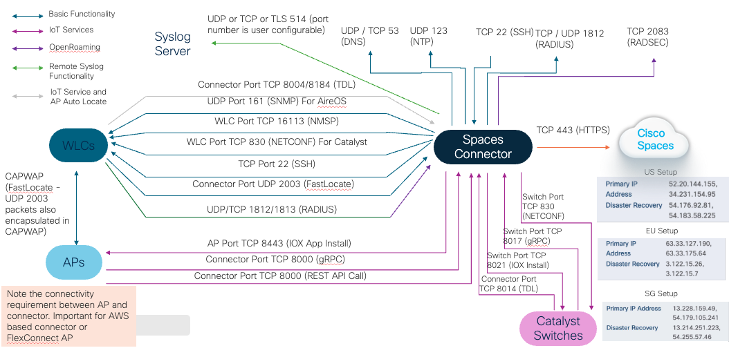
The Cisco Spaces Connector should be able to reach out to the Cisco Spaces endpoints for establishing data connectivity with Cisco Spaces.
The Cisco Spaces Connector must be able to communicate to the WLC on ports:
Normal Operations
-
16113 TCP (NMSP)
-
830 TCP (NETCONF) – only for Catalyst Controllers
-
22 TCP (SSH)
-
(optional) 2003 UDP (FastLocate)
IOT Services
-
8004 TCP (TDL)
-
8184 TCP (TDL)
For IOT Services, Spaces Connector and APs must be able to communicate on the following ports:
-
8443 TCP (IOX App Install)
-
8000 TCP (gRPC and REST API calls)
The above is of particular note to customers with public/private cloud environments
For an in-depth guide into the connector please refer to our Configuration Guide.
The first steps in setting up the Connector are as follows.
It is always recommended, if not required for some outcomes, to use the latest version of the Connector available.
Click here for a video guided demo
-
Download the Cisco Spaces Connector OVA from here: Cisco Spaces OVA
-
Deploy the downloaded Cisco Spaces OVA file on a virtual machine.
-
Once the OVA is deployed, log into the VMware console using the default username and password provided in the console, username: root Password:root
-
Enter the network settings.
-
Optional: Enter NTP settings.
-
Set the password for spacesadmin user.
-
When prompted, reboot the device and open the WebUI using the address provided.
-
Log into the Cisco Spaces dashboard, click on Setup on the Menu.
-
Select Wireless Networks.
-
Click on Add New button .
-
Select Cisco AireOS/Catalyst.
-
Select via Spaces Connector, then select Continue Setup button.
-
Under step 2 Configure Spaces Connector, click on Create Connector.
-
In the Connector Name field, enter a name for the connector and click on Create.
-
On step 2 Configure Spaces Connector, click on View Connectors.
-
A list of Connectors that have been created will be seen. Select the desired Connector.
-
Click on Generate Token.
-
Copy the token that appears on the following screen of the Cisco Spaces dashboard.
-
Launch the Cisco Spaces Connector using the HTTP address provided at the OVA deployment, https://< IP-address >/. In the Cisco Spaces Connector window that opens up, enter the username and password that was configured earlier.
-
On Configure connector place the token, and click save.
It may be needed to wait a few minutes for Cisco Spaces connector to start as images may take some time to download. The wait time is dependent on the speed of the connection
The Connector setup is now complete.
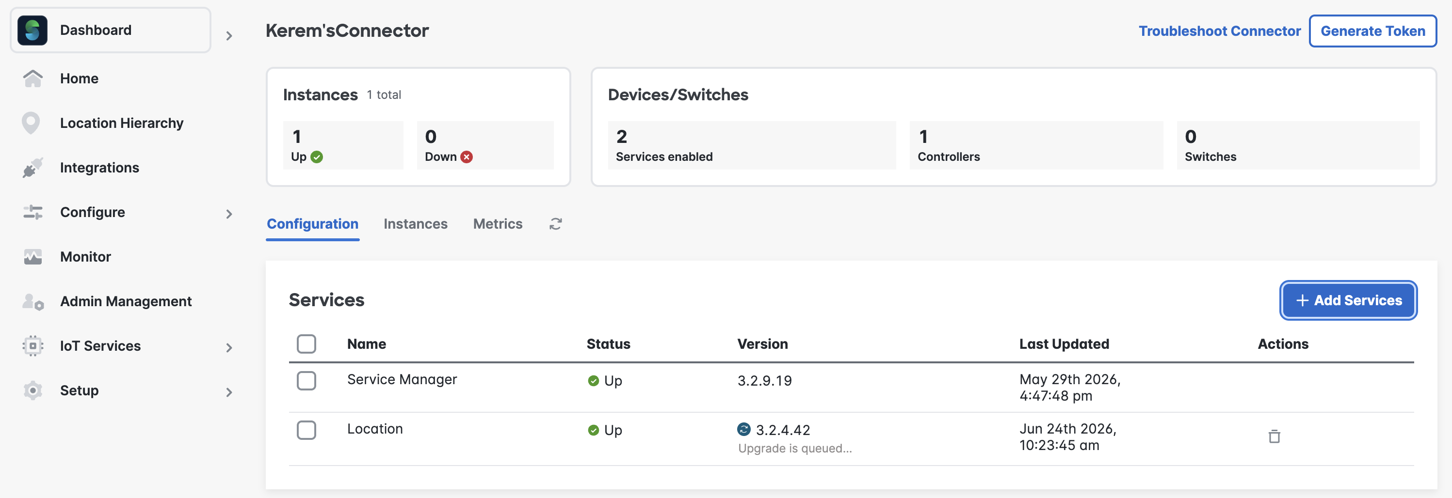
This is how the Connector Dashboard and Cisco Spaces Dashboard will look like once the connector is active.
The connector can be deployed in a High Availability configuration. See the linked guide for instructions and restrictions.
Connector Dashboard
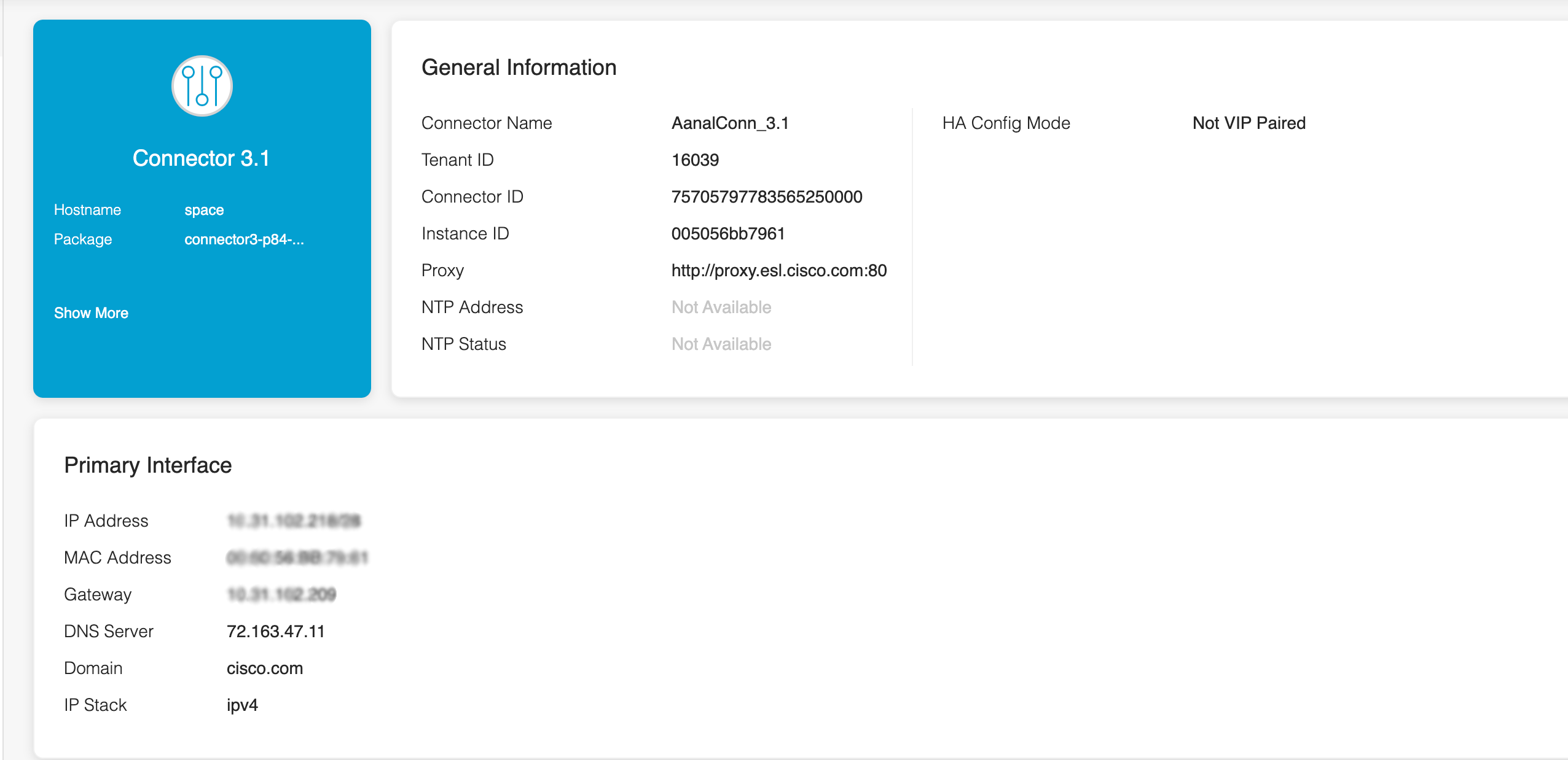
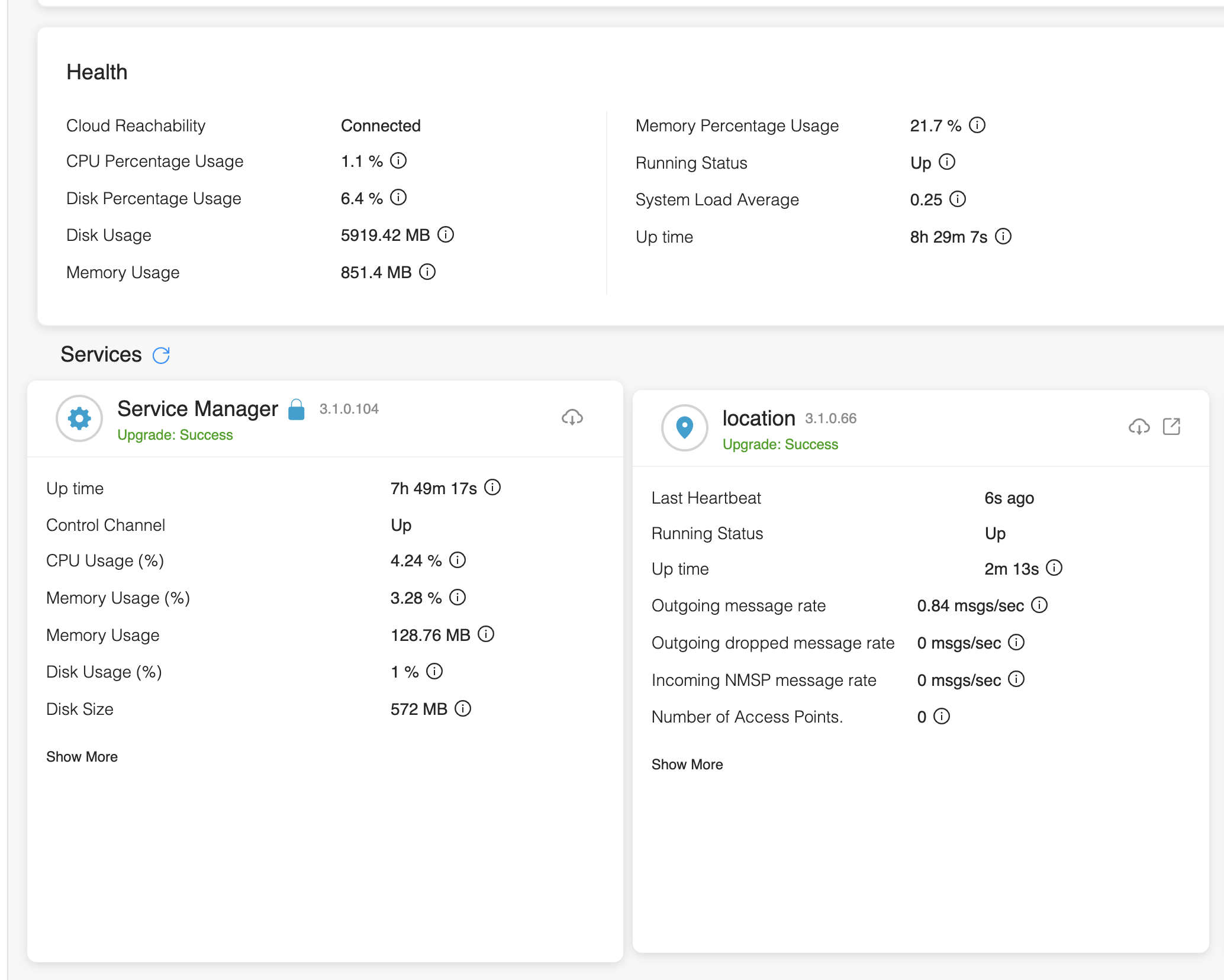
Control Channel: Health of connection between Cisco Spaces Connector and Cisco Spaces Cloud.
Data Channel: Health of connection between Cisco Spaces Connector and Cisco Spaces Cloud.
Cisco Spaces Dashboard
If a more in-depth guide is needed for granular configurations please refer to our Configuration Guide.
WLC
Recommended firmware versions are 17.12.4+ and 17.15.x
Now the Spaces connector is configured, WLC can be added to Spaces.
-
On the Customized Setup page step 3, click on Add Controllers
-
Select the Connector that was just created from the drop-down
-
Add the IP address of the Controller
-
Add the name of the Controller
-
Select Controller Type
-
Add details based on the controller type.
For AireOS WLC – Select Controller SNMP version depending on the controller’s SNMP version. Read/Write permissions are needed for V2C and V3-
For V2C SNMP, provide SNMP Community.
-
For V3 SNMP, provide username, password, select authentication Protocol and enter Privacy password.
-
Enabling the WSA tickbox is used for WIPS purposes in Spaces.
For Catalyst WLC / Catalyst 9800 – Add the following credentials
-
Enter Netconf Username and Password.
-
Enter Enable password of the controller.
-
Verify the interface: NMSP will only be sent from the interface configured as the “wireless management interface”. Interfaces used as a service-port (e.g., gig0/0 for an appliance) cannot send NMSP traffic.
-
-
Click on the Test Connectivity button.
-
Click Save & Add Next Controller if needing to add another controller. If not, click Save & Close.
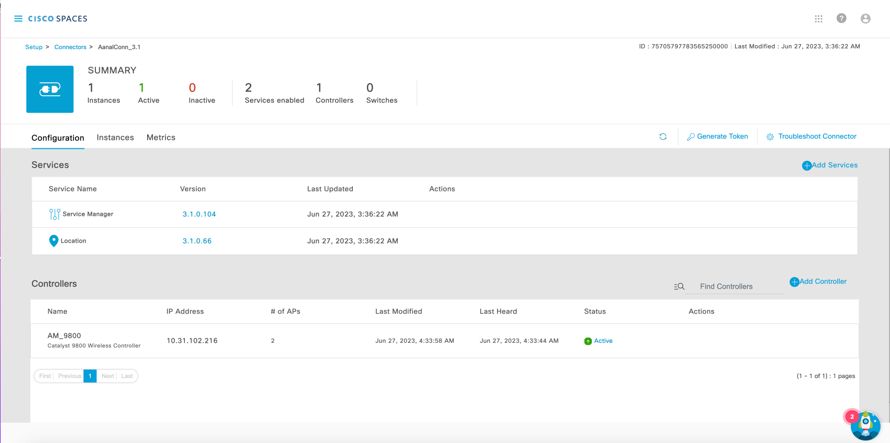
This is how the Spaces dashboard should look once the controller and connector are active.
For an in-depth guide into integrating wireless please refer to our Configuration Guide.
Catalyst Center
Integrating Catalyst Center with Cisco Spaces is the easiest way to setup Spaces for any Catalyst based deployment.
Prerequisites follow:
-
Catalyst Center, Release 2.1.2.3 or higher.
-
Catalyst Center must be able to connect to https://dnaspaces.io:443 for the initial activation. It may also require access to other regions depending on the Cisco Spaces account region.
See below for more details:-
https://dnaspaces.io:443 (IO deployments)
-
https://dnaspaces.io:443 and https://dnaspaces.eu:443 (EU deployments)
-
https://dnaspaces.io:443 and https://dnaspaces.sg:443 (SG deployments)
-
-
Floor plans with accurately placed APs inluding heights and angles accordingly. See https://www.cisco.com/c/en/us/td/docs/cloud-systems-management/network-automation-and-management/catalyst-center/2-3-7/user_guide/b_cisco_catalyst_center_user_guide_237/m_work-with-wireless-2d-and-3d-maps.html for more details.
GPS markers are crucial to Spaces use cases.
It is reccomended to leverage the Network Map Calibration tool within Spaces rather than Catalyst Center for placing GPS markers.
If placing GPS markers on Catalyst Center, ensuring high accuracy is crucial for a number of use cases.
-
Log in to Cisco Spaces, and navigate to Integrations.
-
Under Integrations > Cisco > Catalyst Center select Connect. The Catalyst Center integration will show.
-
When the window appears, click Add Instance.
-
In the dialogue box, input a new instance name and then click Generate.
-
Log in to Catalyst Center, and navigate to System > Settings > External Services > CMX Servers/Cisco Spaces.
-
Next to Cisco Spaces, click Activate, then paste the token into the dialogue box and click Connect.
This should now show a success notification, and the status should show as Activated.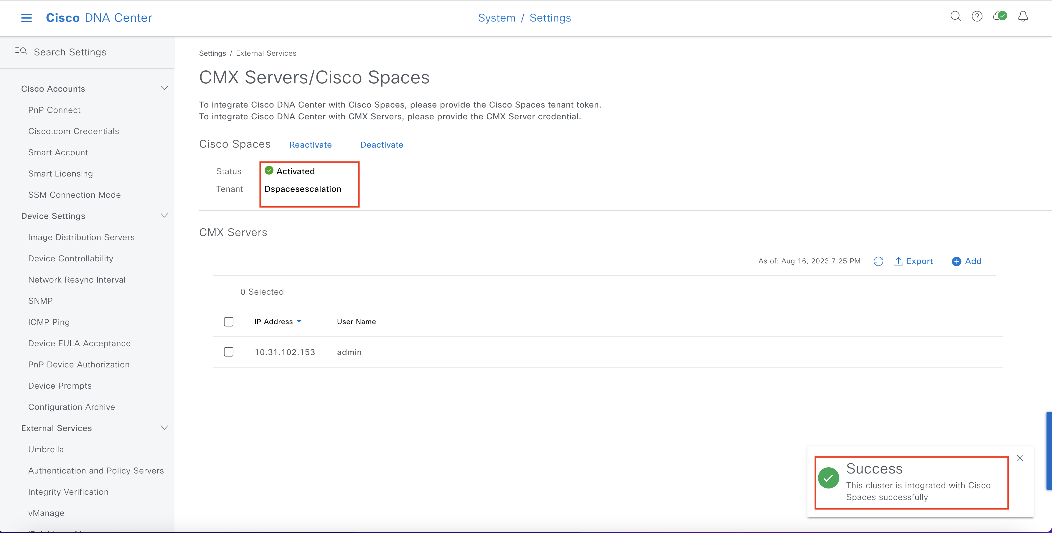
-
Now navigate to Design > Network Settings, and select a location that should be pulled through to Cisco Spaces. Suggestion is to configure at a global level if possible.
-
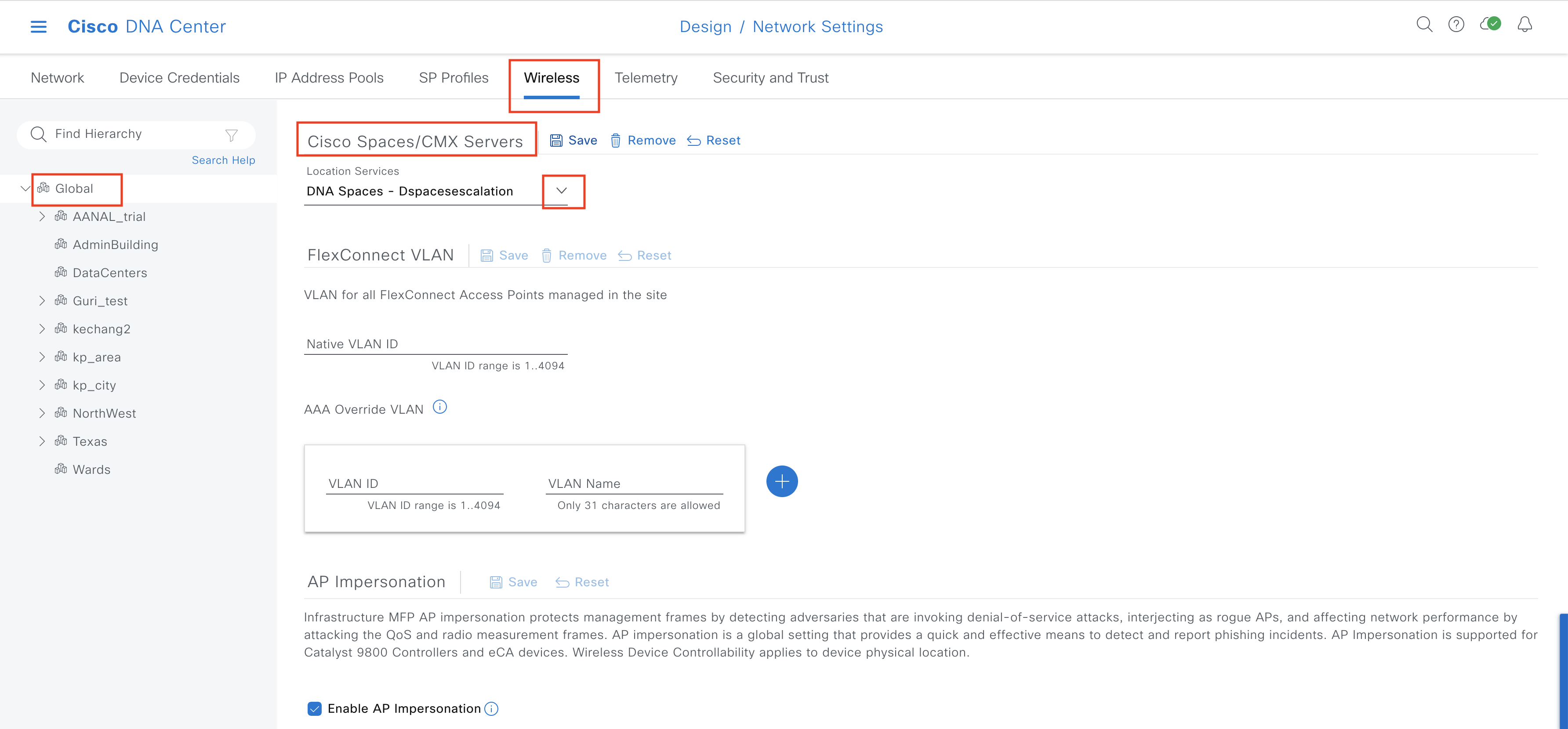
Click the Wireless tab, then in the Cisco Spaces/CMX Server area, choose the service that was configured. This will now trigger a dynamic sync over to location hierarchy within Cisco Spaces.
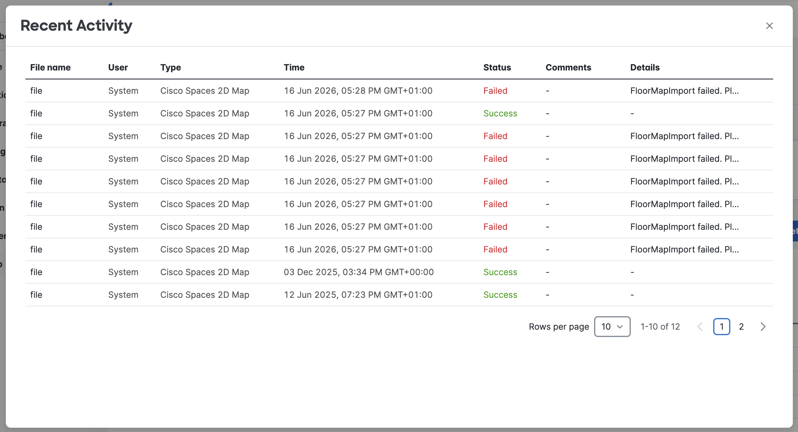
Confirmation of this can be found in Cisco Spaces, under Setup > Locations & Maps > Recent Activity
For an in-depth guide into the integrating with Catalyst Center please refer to our Configuration Guide.
Meraki Wireless
Meraki Wireless
This integration enables to seamlessly connect the Meraki Account to Cisco Spaces via the Meraki Dashboard – in just a few clicks.
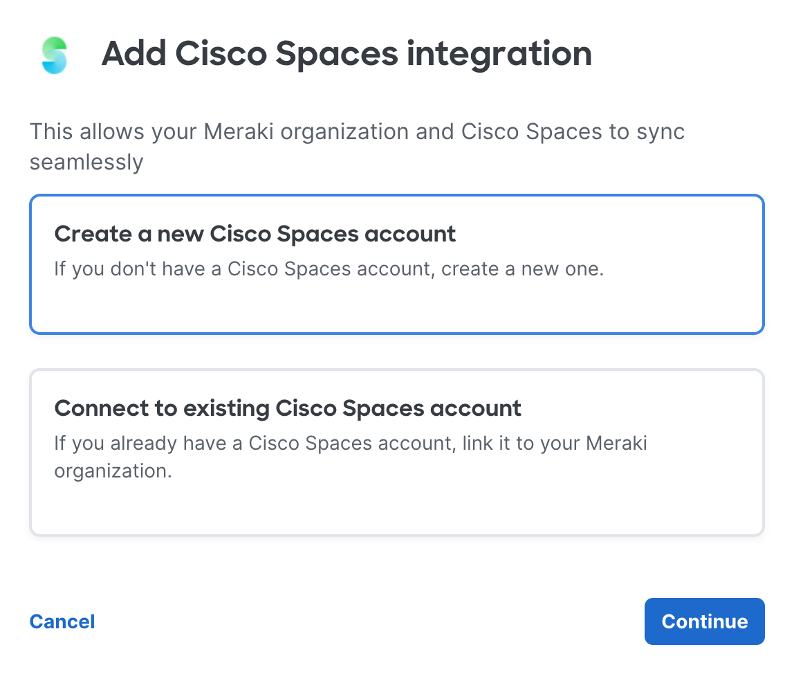
There will be an option to select to integrate into an existing Spaces account if you have one,or to create a new one.
Meraki Wireless Prerequisites
-
Meraki Organization admins with read/write access (SAML admins are not supported)
-
One building per network
-
Floor maps placed accurately against real world both in scale and location
For optimal performance and being able to use all Cisco Spaces capabilities, it is preferred that the Meraki setup have maps with APs placed on them. However, if there are no maps with APs placed on them, Cisco Spaces core analytics features and seamless onboarding features will work.
-
APs placed accurately on floor maps. Follow these articles to place APs accurately
-
Meraki account must be in commercial domain (http://meraki.com). Meraki accounts with the following domains are not supported:
-
Canada = meraki.ca
-
China = meraki.cn
-
India = meraki.in
-
FedRamp = api.gov-meraki.com
-
-
APs must be able to reach the following endpoints on port 1883
-
mqtt.dnaspaces.io (For IO deployments)
-
mqtt.dnaspaces.eu (For EU deployments)
-
mqtt.dnaspaces.sg (For SG deployments)
-
Below are some references to help complete prerequisites:
To configure the Meraki Spaces Integration
-
Log in to the Meraki dashboard, Navigate to Organization > Integrations
-
Go to Under the Browse tab, Click “Connect” on the “Cisco Spaces” tile
-
Under the Browse tab, Click Connect on the Cisco Spaces tile.
Once the integration is completed, navigate to Spaces>Setup>Wireless Networks. Under Connect via Meraki Integration, 1) Connect your Meraki, you should see a green icon next to your organization. Example:
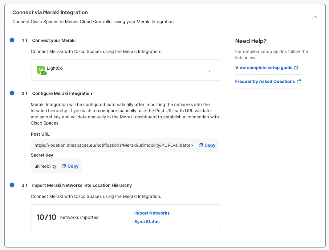
Under 3) Import Meraki Networks into Location Hierarchy, verify that all of the networks (or the ones you’ve tagged with “CiscoSpaces”) have been successfully imported.
Webex Control Hub
Webex Control Hub
Integrating Webex Control Hub with Cisco Spaces allows for granular detail on room occupancy, alongside other use case such as environmental metrics.
The following is a summary of the implementation of work needed to integrate Cisco Spaces and Webex Control Hub. The rest of this section will dive into detail on each of these steps. For more information, continue through this section
Prerequisites
-
Devices should be in workspaces
-
Workspaces should be on floors, with locations configured with correct building names and addresses
-
One building per location(The above is covered in the Location and Maps section below)
-
Devices should be configured with the following details:
-
People Count Out of Call → ON
-
People Presence Detector → ON
-
Ambient Noise Estimation > Interval → 10
-
Ambient Noise Estimation > Mode → ON
-
-
Workspace > Settings should be as follows:
-
Allow Control Hub to capture workspace metrics from device sensors → Checked
-
Enable sensor data configurations on all supported devices → Checked
-
-
All Workspaces should have capacity set correctly
-
All Workspaces should have space type set correctly
Below is a guide covering how to ensure your environment is configured as per best practises, and to align with the prerequisites
Intro to Locations in Webex Control Hub
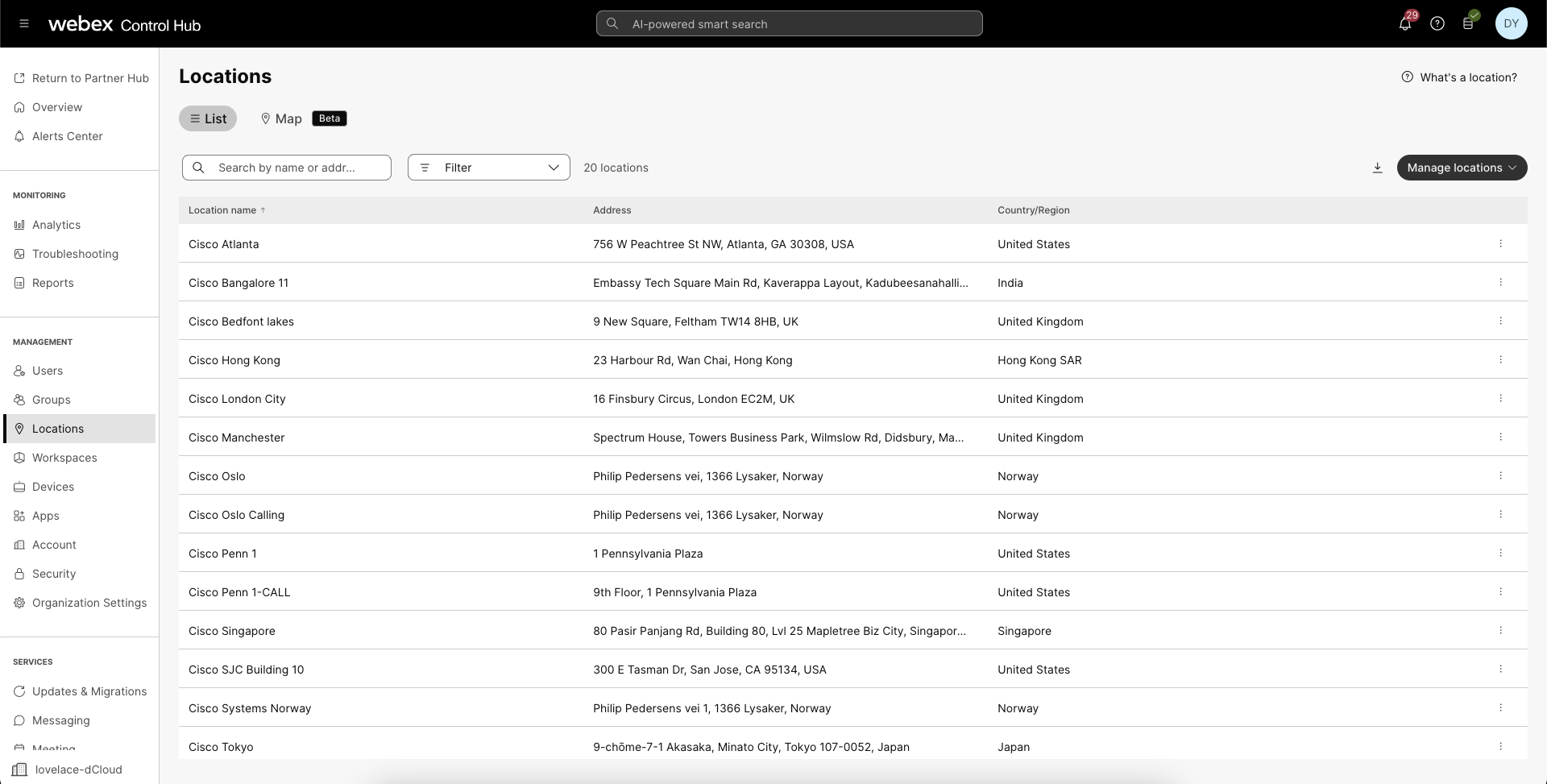
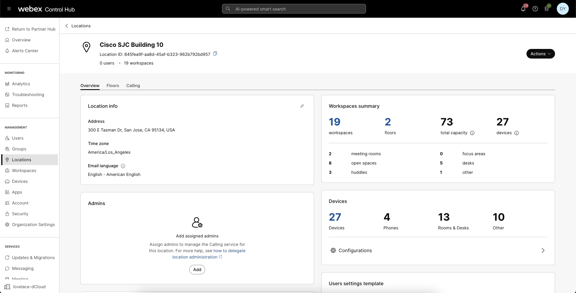
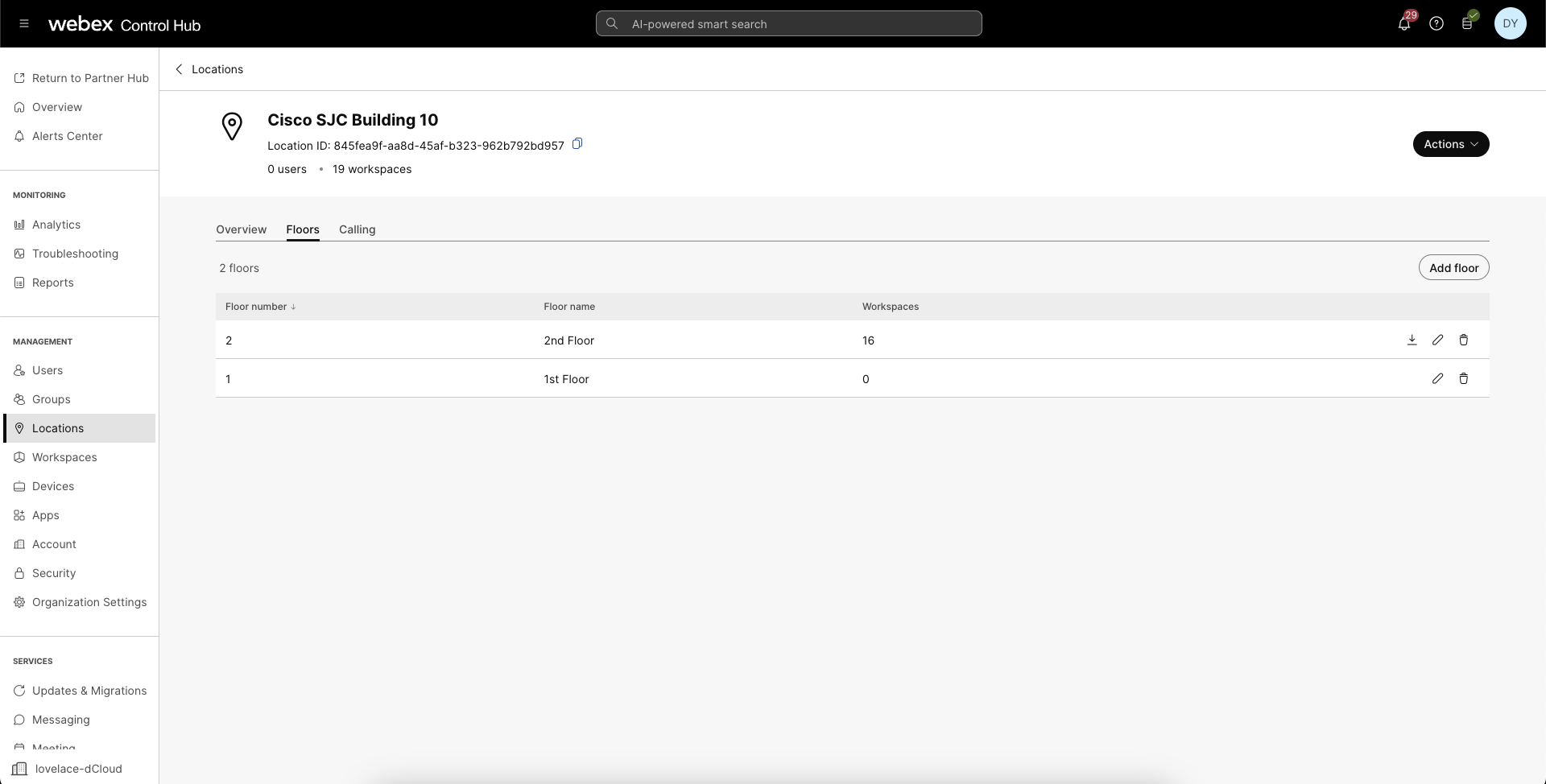
Setting up the structure of Control Hub Locations and Floors is an essential part of the Cisco Spaces integration. A improper structure can add weeks to deployments, result in a degraded end user experience across various outcomes (e.g. Kiosk, Wayfinding, etc.), and cause major downtime to setup properly.
Locations in Control Hub are important for many reasons, including setting up Webex Calling, but the way they are setup and structured can impact other use cases. For example, placing all devices across a campus of multiple buildings into a single Location may result in a Floor list with multiples of Floor 1, Floor 2, etc. For use cases such as Kiosk and Wayfinding, buildings are distinct entities that must be split into separate Locations with their own unique/non-duplicate Floor numbering in order to draw paths and route end users mirroring the physical world. Splitting an existing multi-building Location in Control Hub may result in Webex Calling disruptions and/or added time for setup.
Meanwhile, there are advantages in Cisco Spaces when Control Hub Locations and Floors are setup properly. For example, when a device is organized under a Location > Floor > Workspace, connecting that device to a room becomes easier. Space Manager > Manage Rooms (Space Management) uses a combination of that organization and fuzzy string matching between the Meeting Room name (from the CAD file) and the Webex Workspace name to auto-connect them and use the device for room occupancy outcomes. This automation can save many hours or days of work.
Workspace Configurations
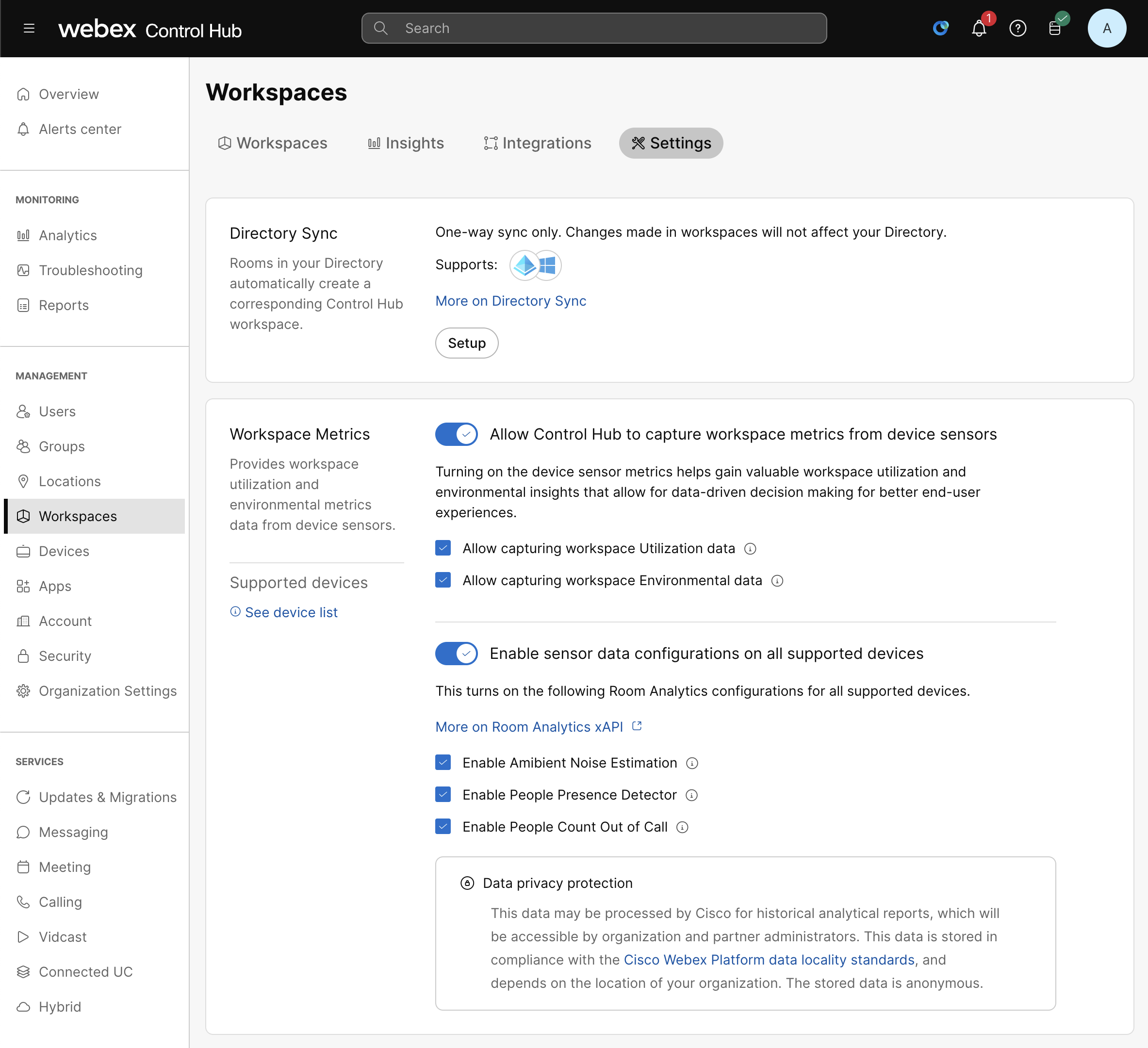
Enabling required global workspace settings
-
Go to Workspaces > Settings.
-
Check Allow Control Hub to capture workspace metrics from device sensors
-
Check Enable sensor data configurations on all supported devices
Bulk assigning capacity to workspaces
-
Select Workspaces (from left nav menu) then enter the Workspaces tab across the top.
-
Select all workspaces with the same capacity, then click edit. A new window will appear.
-
Under Workspace Settings > Capacity, set the value for capacity.
-
Once configuration is finished, click Next.
-
Review the configuration, then click Apply.
-
Ensure configuration took effect with no errors, the click Close.
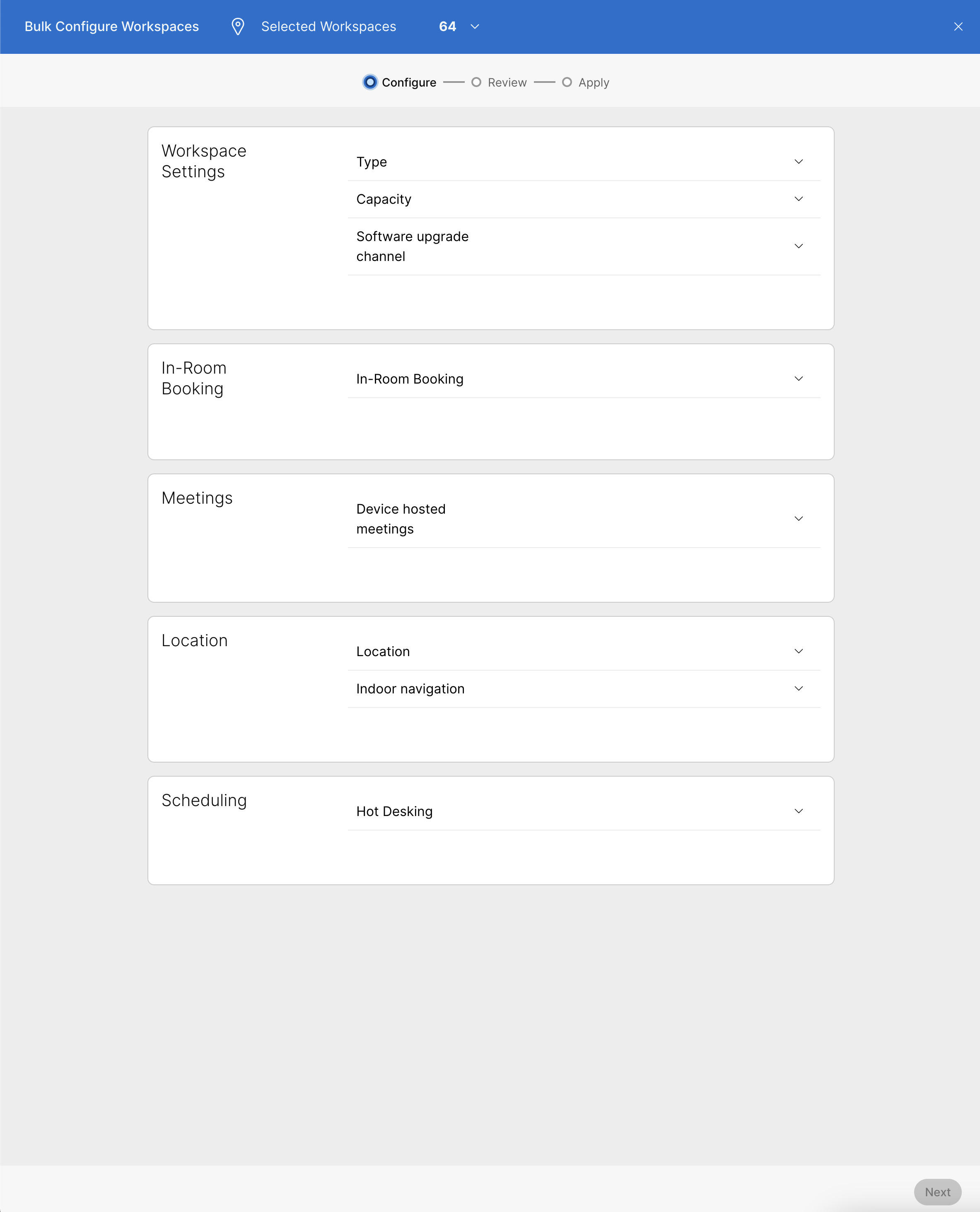
Bulk assigning space types to workspaces
-
Select Workspaces (from left nav menu) then enter the Workspaces tab across the top.
-
Select all workspaces for a given type (E.G. Meeting rooms), then click edit. A new window will appear.
-
Under Workspace Settings > Type, set the type as required.
-
Once configuration is finished, click Next.
-
Review the configuration, then click Apply.
-
Ensure configuration took effect with no errors, the click Close.
Device Configurations
Bulk enabling required device settings
-
Head to Devices (in the left nav) and select all required devices.
-
Click Edit and a new right hand panel will open. Select All configurations
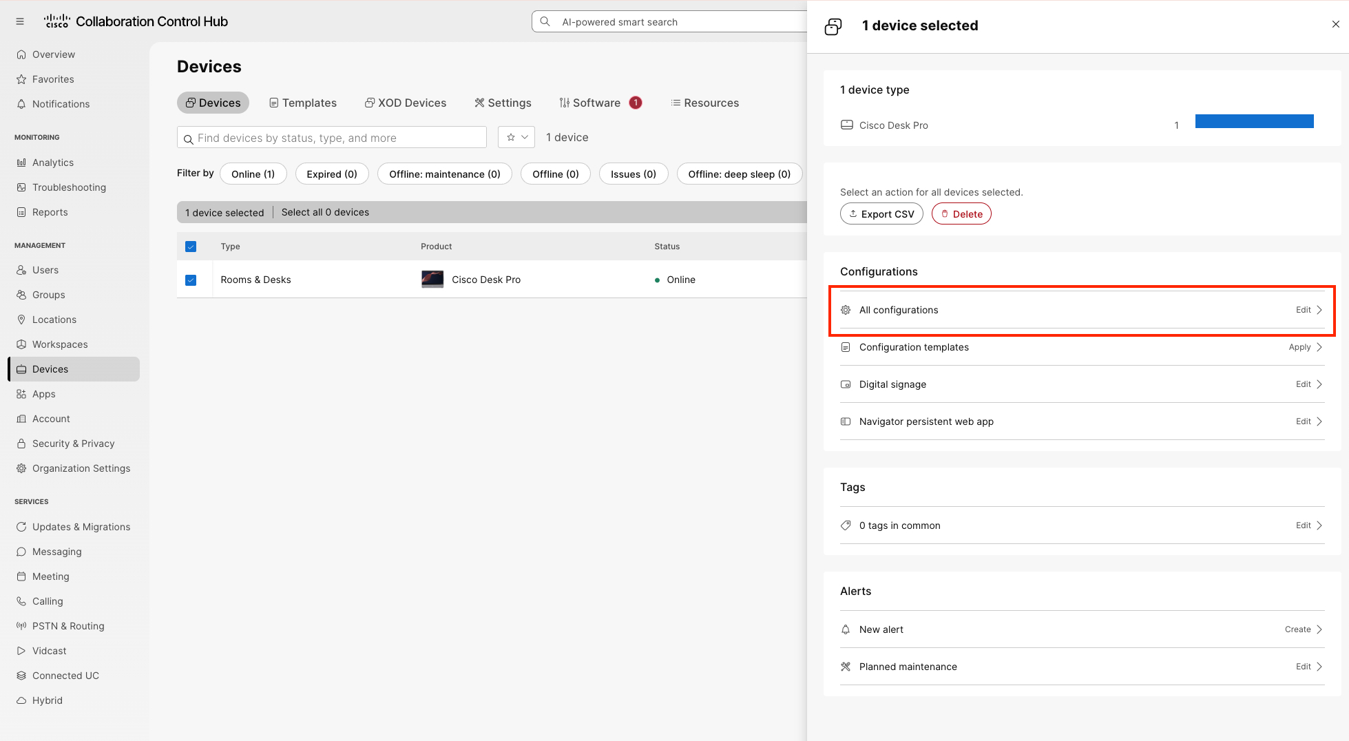
-
On the new page that appears, apply the following configuration:
-
People Count Out of Call → ON
-
People Presence Detector → ON
-
Ambient Noise Estimation > Interval → 10
-
Ambient Noise Estimation > Mode → ON
-
-
Once complete, click Next
-
Verify changes and click Apply
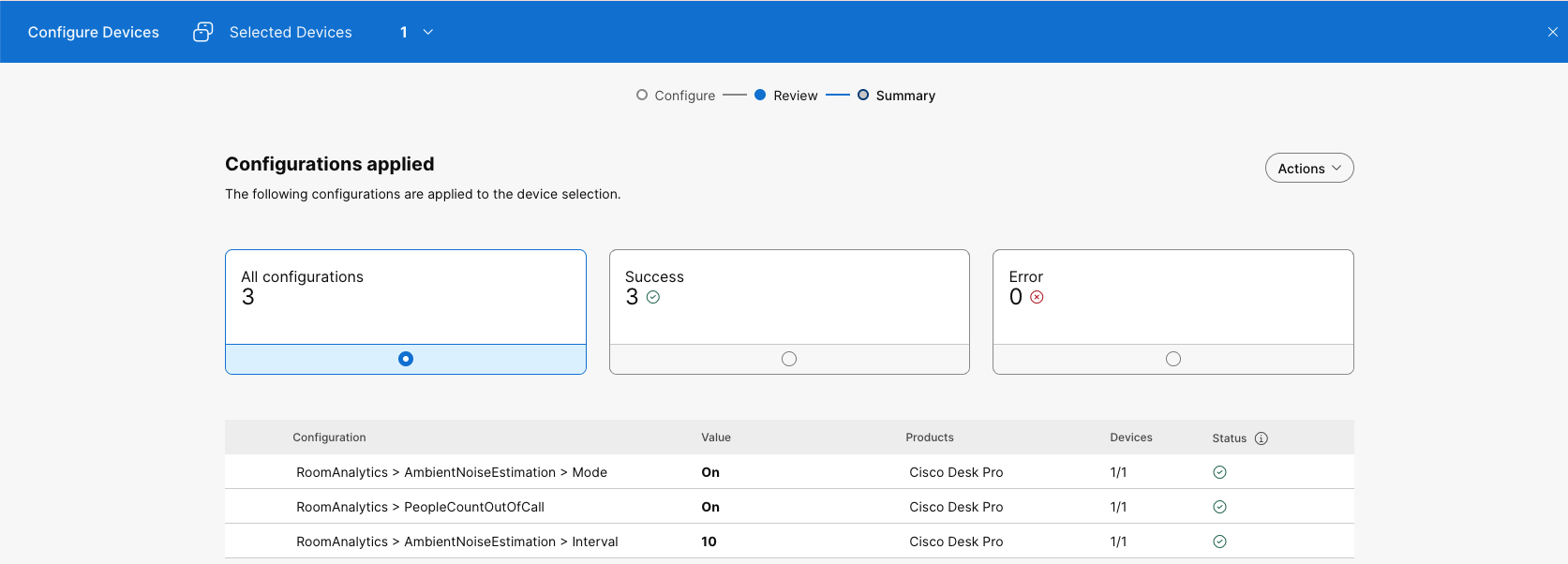
-
Verify that all changes have been applied and there are no errors, then click Close.
Integration
This integration will allow telemetry from selected workspaces to be sent directly from Control Hub to the Cisco Spaces account. This will power room occupancy, booking status, in-room environmental metrics, etc.
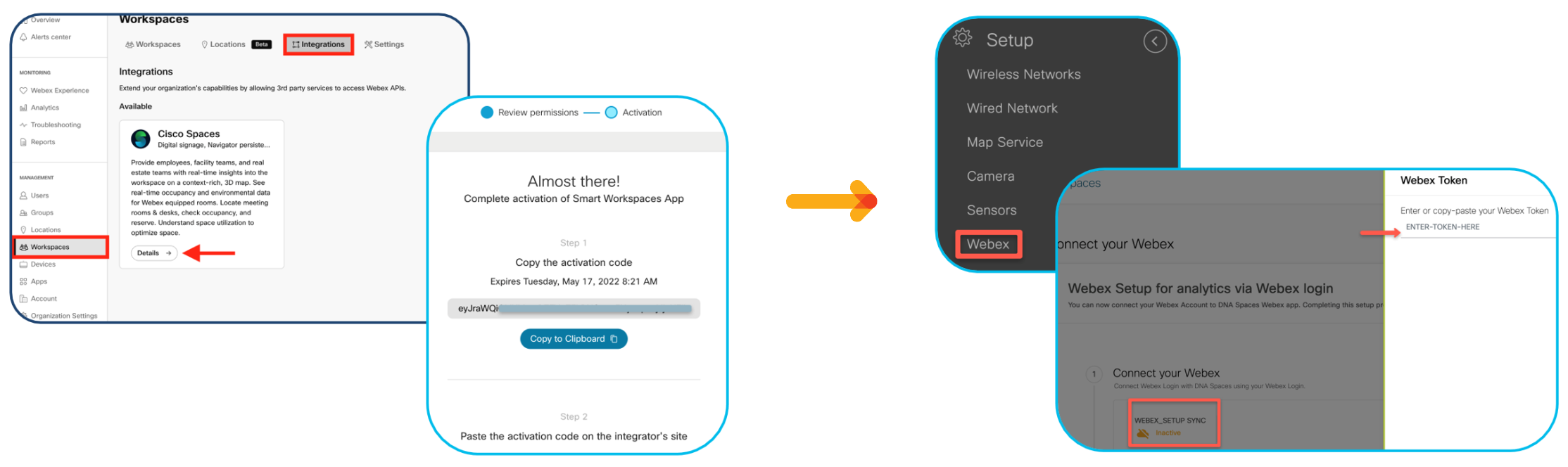
-
Log in to Cisco Webex Control Hub and navigate to Workspaces > Integrations.
-
Find the Cisco Spaces app tile and click Details.
-
Scroll down to review the permissions required (i.e. xAPIs).
-
Check the box to accept the Terms and Conditions.
-
Scroll to the bottom right corner of the page and click Activate.
-
Click Copy to clipboard.
-
Navigate to Setup > Webex in the Spaces dashboard.
-
In the Connect your Webex window, click Connect.
-
In the Enter or copy-paste the Webex Token field, enter the Cisco Webex token, and click Connect.
-
This will result in a sync between Webex Control Hub and Cisco Spaces.
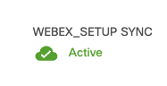
The Cisco Webex synchronization status will display as Active for all active users in a specific tenant (account) if at least one user successfully connected their Cisco Spaces account with the Cisco Webex account while importing the Cisco Webex networks into Location Hierarchy.

Configuring the Location Hierarchy

The Location Hierarchy allows businesses to organize their buildings into a recognizable and consistent structure. Cisco infrastructure and sensor telemetry will then be combined, normalized, and standardized into a structure regardless of separate hierarchies across other platforms (e.g. Catalyst Center, Prime, Meraki Dashboard, Webex Control Hub). The hierarchy can be organized based on specific brands, regions, campuses and other taxonomies that are relevant to the business.
By translating the IT network view into a business view, it can be automatically presented with a cleaner business relevant insights report. Any changes to the network topology are automatically reflected here thereby making it easy to manage.
Important: How the Location Hierarchy is structured is as much cosmetic as it is functional with wide-ranging effects in applications and outcomes. Proceed with caution before Creating and/or Merging the Location Hierarchy. Making corrections later can result in lost data and service disruptions to end users. Consult with the Cisco Spaces team if there any doubts or would like to consult on the best practices given your specific environment details.
Recommended Route
We recommend following geographical hierarchy as follows:
-
Continent or bigger (e.g. Europe, EMEA, APAC)
-
Country
-
Region (e.g. state, county, city)
-
Campus (only if multiple buildings on a single site)
-
Building
-
Floor
The above is the end goal. The below is the priority of sources in order to achieve this goal.
In order:
-
Catalyst Center and/or Excel template
-
Meraki Dashboard
-
Webex Control Hub
Recommendation is to fix any issues with hierarchy in Catalyst Center where possible, rather than using the excel to fix the missing elements.
Excel is the most flexible method, but requires the most manual configuration. You should use it to add missing hierarchy elements, but not to build the entire hierarchy from scratch.
Managing and Merging the Location Hierarchy
Spaces should have by now ingested hierarchies from all integrated platforms: Catalyst Center, Meraki Dashboard, and Webex Control Hub.
Note: you will see Catalyst Center, Prime, and Meraki Dashboard Locations + Floors (and network maps) appear in the Cisco Spaces Location Hierarchy automatically. While data may start to populate in some applications from the time of integration and initial setup (e.g. Connector), there are required steps to Create and/or Merge the network hierarchies into the official Location Hierarchy. Follow these steps to make the Location Hierarchy Creates and/or Merges permanent, and to upload CAD files to create Digital Maps for other outcomes and use cases.
This section is designed to merge those hierarchies into a single, business focused hierarchy, to use across the Spaces platform.
-
If there is an existing location Hierarchy it can be viewed under Setup > Locations & Maps.
-
Click on Review.
-
Click on the > sign to expand and review the locations.
-
Click on the drop-down under Action.
-
Choose 'merge with’ to merge same location hierarchies that would have been previously created.
-
Choose the location that needs to be merged from the dropdown under Existing Locations.
This configuration is hierarchal, meaning configuring this at a campus level, will also configure the same at all buildings and floors below. This can be changed manually on a per location basis as needed.
-
Click Next and Select Agree and continue once reviewed.
-
Review changes and click Merge.
For an in-depth guide into the Location Hierarchy please refer to our and Setup Guide and Knowledge Article.
Configuring Metadata
Location Hierarchy Metadata
Meta data is needed for computing accuracy of occupancy at the platform level. See the table below for elements that need configuration.
-
Login into Cisco Spaces and go to Location Hierarchy.
-
Navigate the hierarchy and select a location.
-
Select the Location Info tab
-
Click the blue Edit button next to Location Data.
-
Configure elements as needed, then click Update.
-
Click Save.
-
Continue to configure location data as needed. It is recommended to configure location data for every element within the location hierarchy.
Metadata configuration is hierarchal, meaning config applied at a campus level, will reflect down into respective buildings and floors. This is most relevant for config such as brand, or timezone, and less relevant for config such as area, which will change throughout the hierarchy.
|
Location Hierarchy Metadata |
|
|
Timezone (Mandatory) |
Has to be defined at the network level. Computation defaults to GMT if time zone is not set. Impacts ‘time of day’ and daily counts among other metrics. |
|
Occupancy Limit (Max Capacity) (Mandatory) |
Critical for computing % utilization Normalizing occupancy data for better cross location comparison Seating capacity= no. of seats/workstations assigned for a particular floor/building Has to be defined at network and floor level. |
|
Area in Square Feet / Square Meter (Suggested) |
Used to compute density. Normalizes occupancy data for better cross location comparison |
Live Occupancy Metadata
Filtering is another element that is required for accurate occupancy data. As people typically carry multiple devices with them that connect to the network it is essential that there is a method to understand how to get an accurate count for each person, rather than each device. Look below at the table for such methods.
For more insight on what to configure here, and how people counting works, see https://runbooks.ciscospaces.io/docs/counting-people-from-wi-fi
-
Log into Cisco Spaces and navigate to Live Occupancy > Settings.
-
Select the blue pencil next to excluded SSIDs from Live Occupancy analytics.
-
Select all SSIDs that employees do not connect to. Use the guidance below to help determine which SSIDs to select.
-
Click Save.
|
Live Occupancy Settings |
|
|
Excluded SSIDs from Live Occupancy analytics (Mandatory) |
Exclude all SSIDs which employees (or students for universities) do not connect to. Recommend excluding Guest SSID’s for two reasons:
|
|
Categorize Visitors (Suggested) |
Categorizing visitors allows configuring which SSIDs are used for what purpose. SSIDs can be configured as:
These visitor categorizations are used within the Live Occupancy and Visitor Trends apps, and configuring them can give deeper understanding into the type of visitors within an environment. |
Digital Map Creation & CAD File Upload

Upload, process, and publish Digital Maps
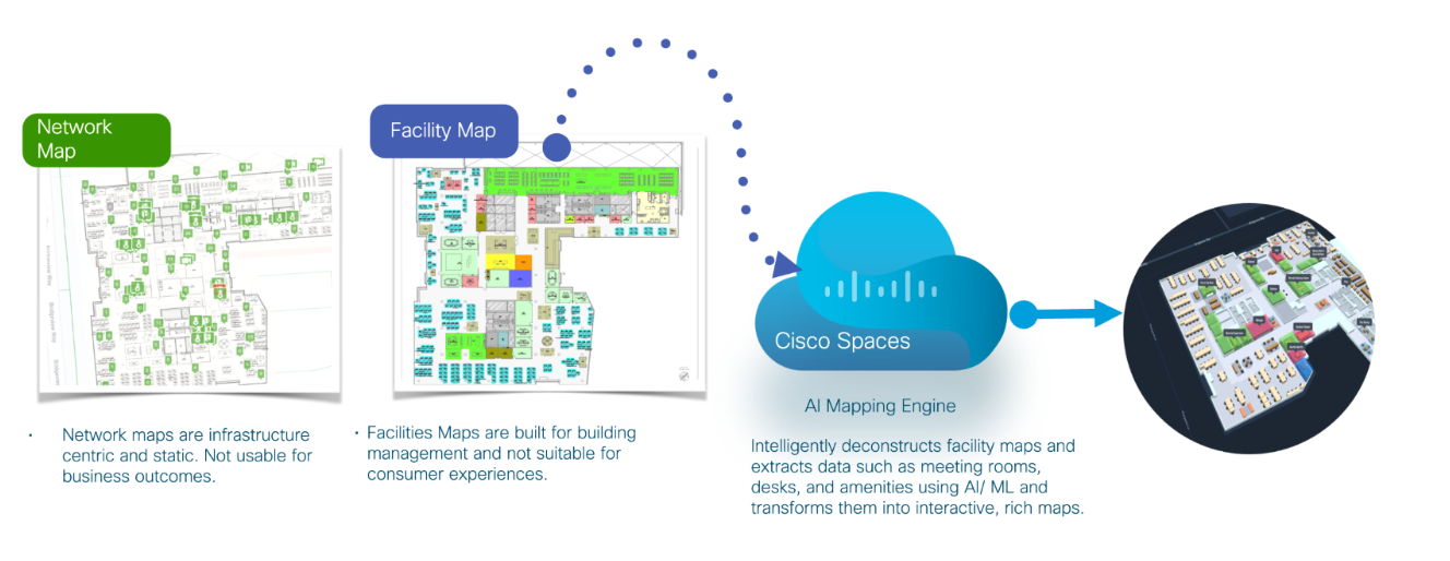
Once the Location Hierarchy is created, merged, and unified across multiple sources, the next step is to upload CAD files (.dwg) or Vector PDFs to generate a Cisco Spaces Digital Map.
After uploading it can take up to 1 week for processing workspaces / office floorplans. Very large buildings and other maps (e.g. venues, retail, healthcare, education, manufacturing, etc.) can take longer, such as 3-4 weeks.
Prerequisites
-
License: Cisco Spaces Advantage, Premier or Premier with Collab & Wireless
-
One CAD or Vector PDF file per floor
-
Separate layers:
-
Architectural layer
-
Funiture layer
-
Space names/IDs/Labels
-
For Digital Maps best practices, please read our knowledge article: https://runbooks.ciscospaces.io/docs/digital-map-pro-and-cad-dwg-pdf-best-practices#Wayfinding-Custom-POI-and-Path-Editor---Early-Preview-(August-2025)
STEP 1: Under Setup > Locations & Maps
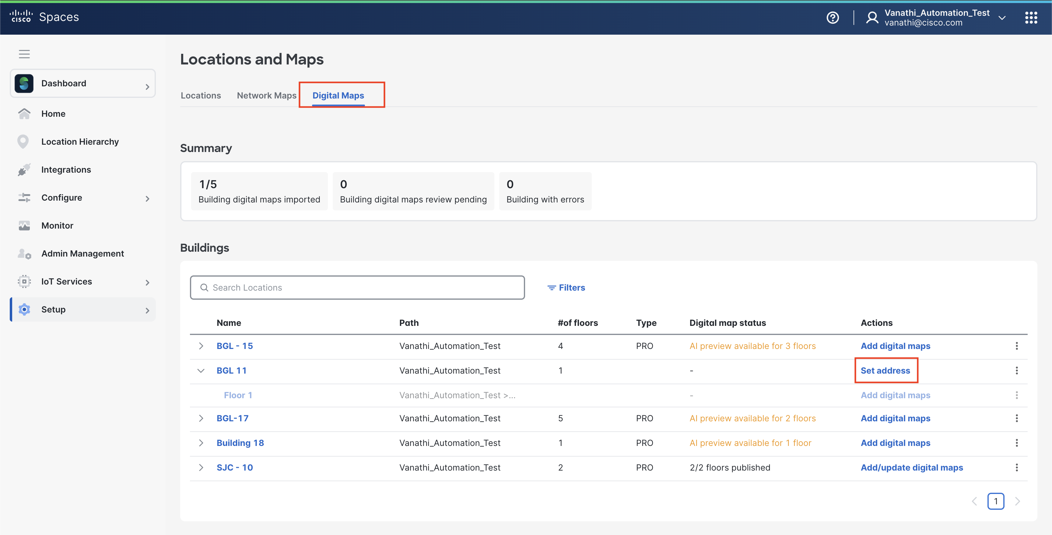
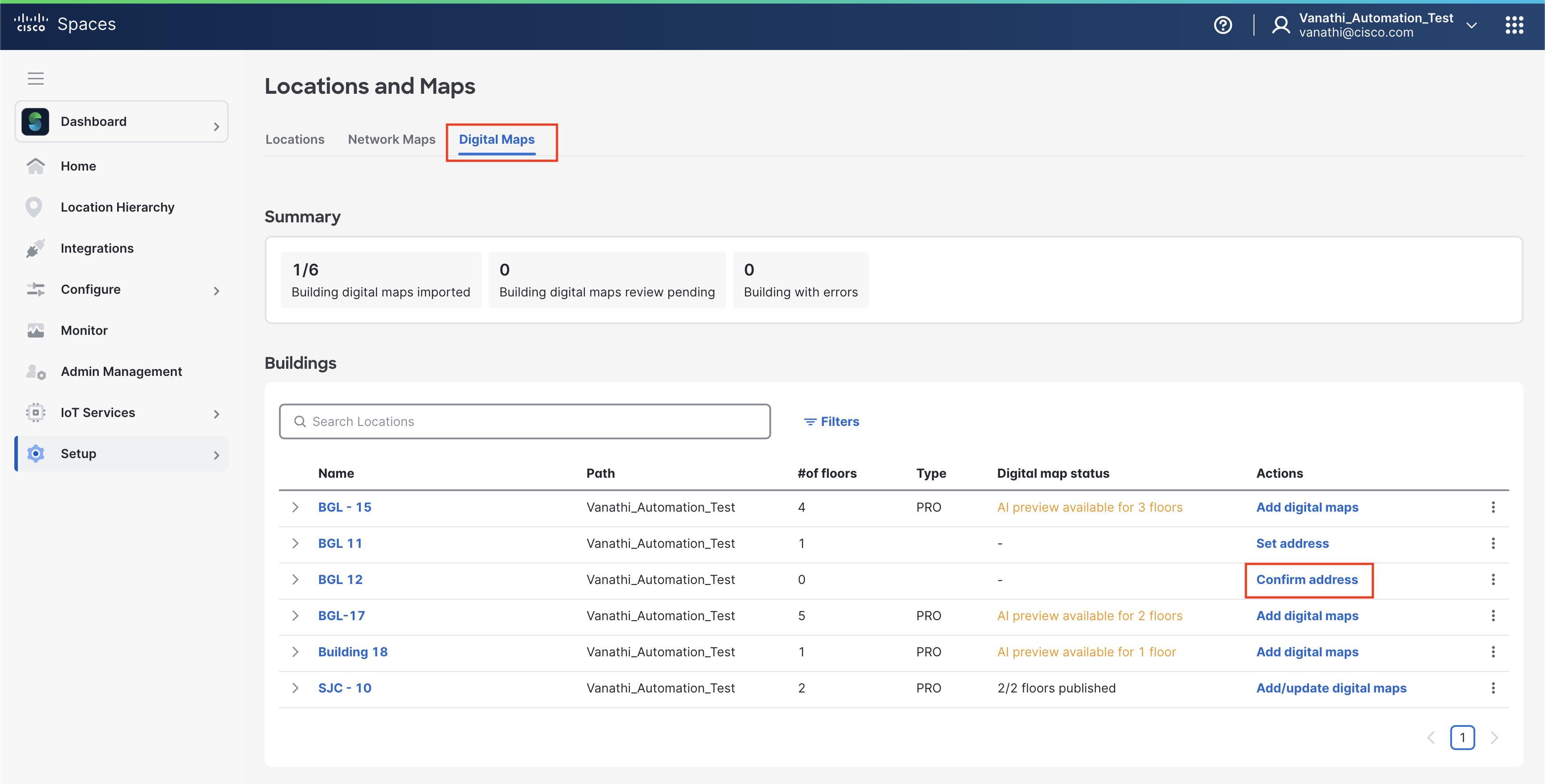
Click on the Digital Maps tab. Either search or choose your desired building and Click Set address if no address is added, or Confirm address if the address is present but unconfirmed.
STEP 2: Set address / Confirm Address:
Provide and confirm the correct building street address using Google address autocomplete.
Click in the street address field and select the correct address from the dropdown for the best results
Verify if the location pin is at the right location, if not, you can drag and drop the pin on the center or the focus area of the building. This will be the default center or focus area in other Spaces apps. Click on “Update”. Locations with an incorrect street address (must match the physical building outline) will be rejected.
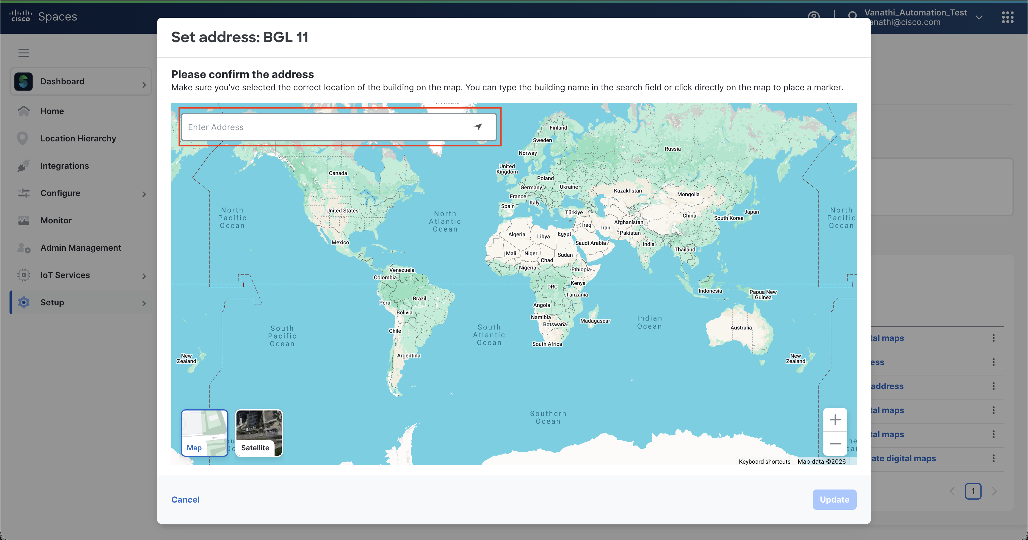
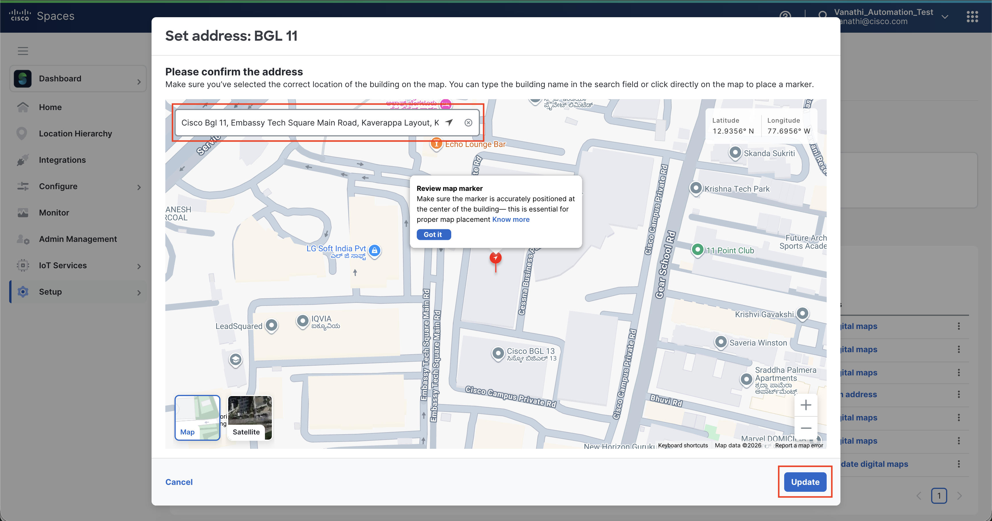
STEP 3: Create floors by Clicking on “Add/update floors”.
Floors created or merged from Catalyst Center, Prime, Meraki, or Webex Control Hub may already be populated on this page.
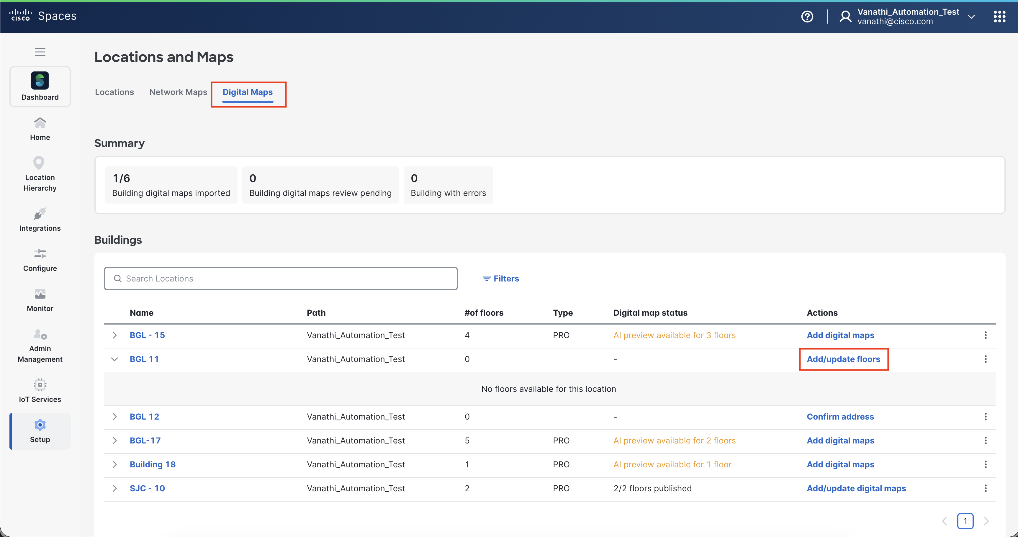
STEP 4: Click on Add new floor to add new floors
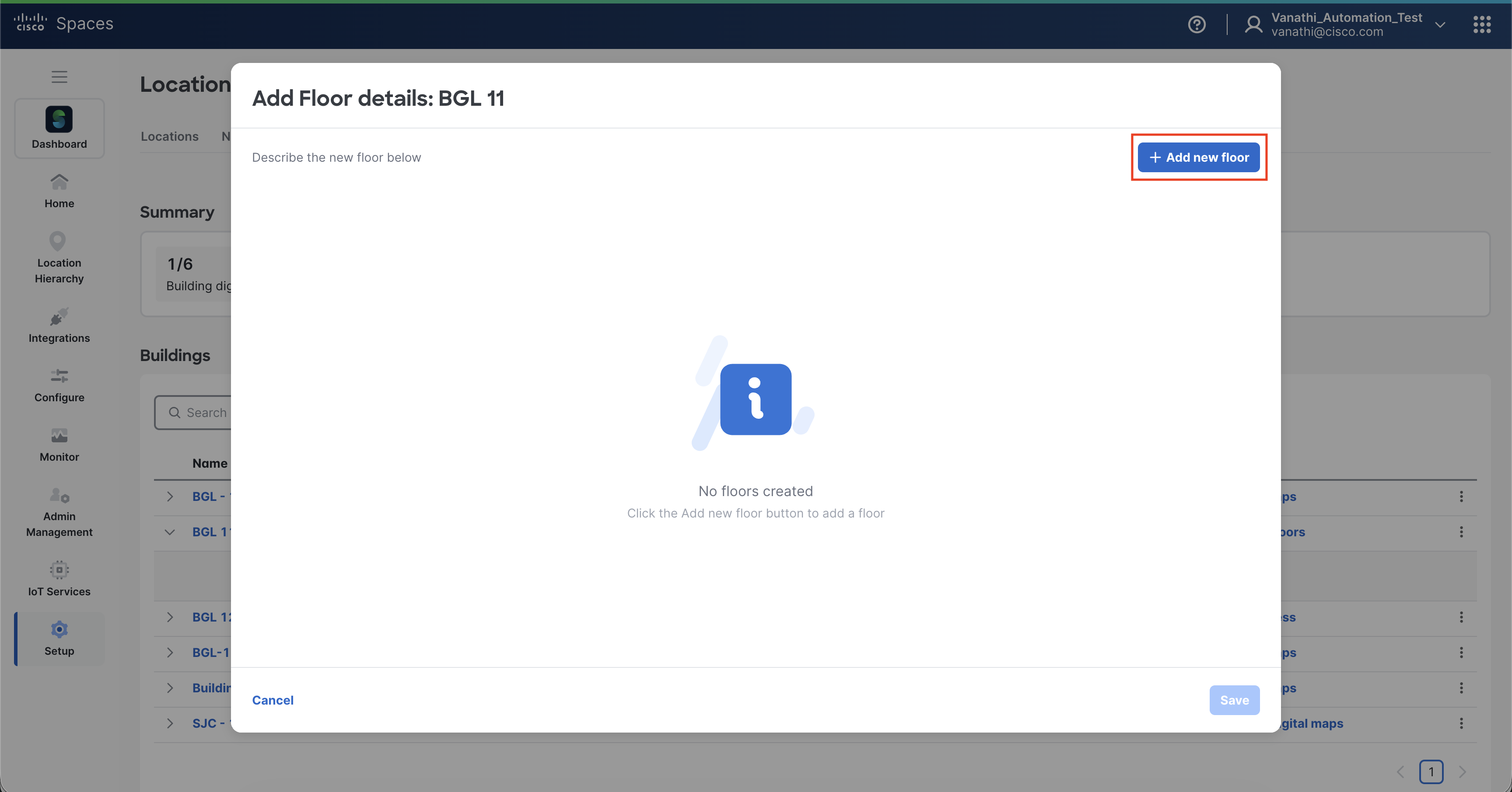
STEP 5: Add missing metadata to the floors. Enter floor details and level number. Ensure that all floors are accurately listed with their corresponding level numbers and short names, as these cannot be modified until the map has been processed and published; however, once the map is processed and published, the metadata can be modified.
“Level Number” cannot be duplicated within a building. Floors must either be combined or split up at the source (e.g. Webex Control Hub, Catalyst Center, Meraki Dashboard). This metadata has a significant impact on apps such as Wayfinding, Kiosk (Signage), etc.
Verify floor and Click “Save”
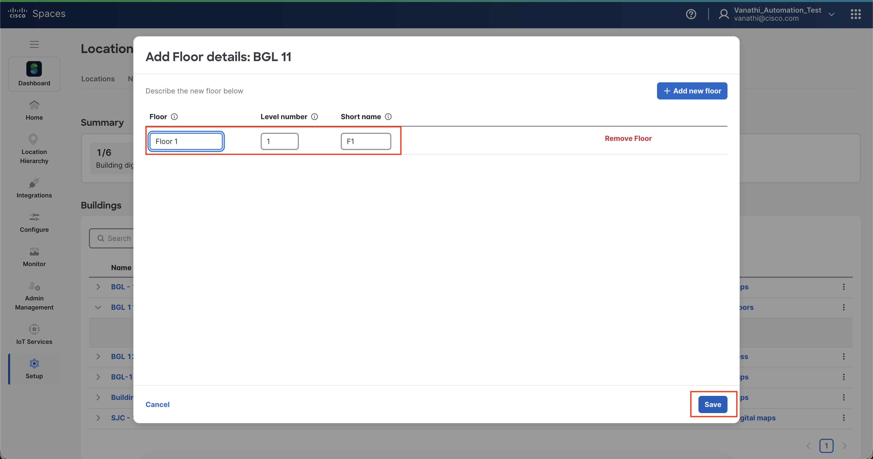
When naming floors, choose a naming convention that is familiar to your end users. Repetitive information, such a building name, may not be necessary in the Floor Name and/or Short Name if the building name already appears in the UI (e.g. Kiosk, Space Explorer Web App, Wayfinding App Clip/App). There is a 5 alphanumeric character limit in the Short Name, and Level Numbers must be numerical whole numbers. A good rule of thumb for Short Name is to replicate what you may see in an elevator floor button panel, or a placard in a stairwell indicating the current floor.
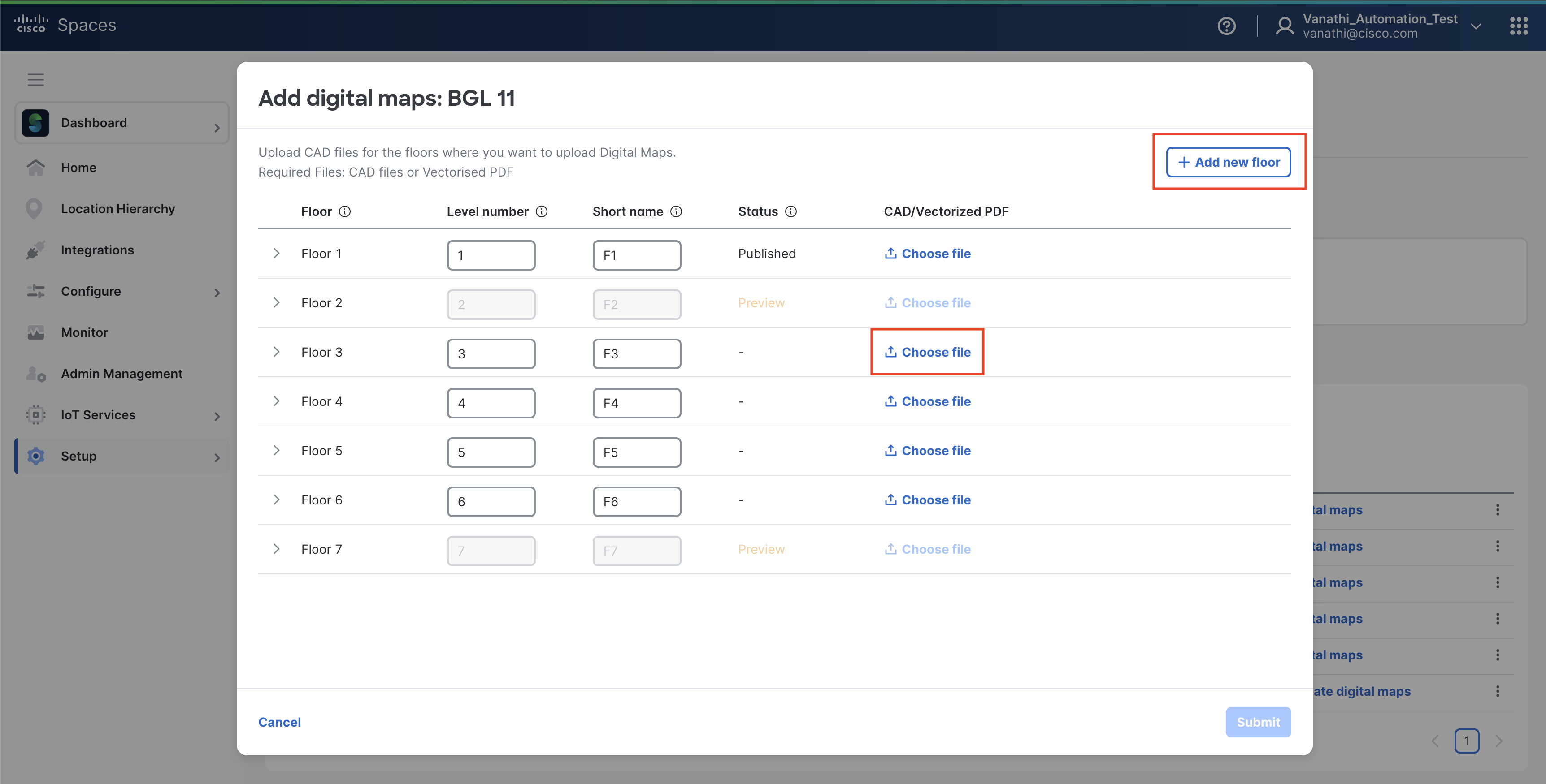
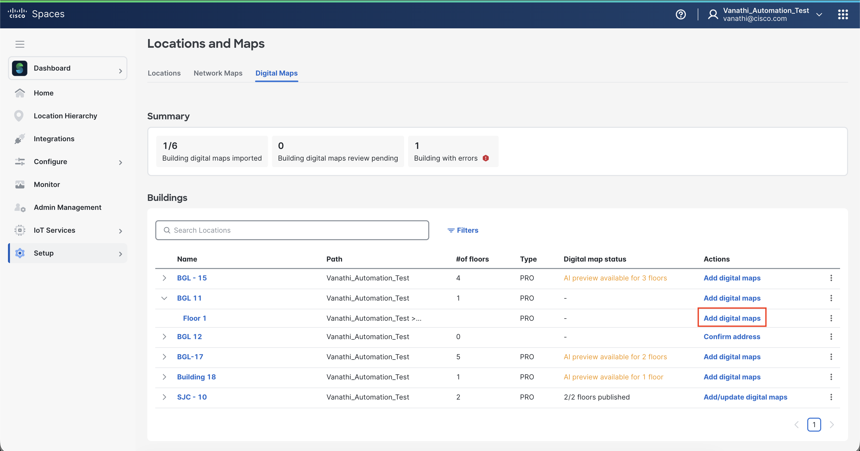
STEP 6: Click Add Digital Maps for the desired floor or multiple floors at the building level to upload your CAD or Vector PDF files.
Add Digital Maps - multiple floors at the building level
Add Digital Maps - multiple floors at the building level
Click Choose file to upload the CAD file, then click submit.
You can add new floors and edit existing floor details.
Editing is allowed only for floors that are not currently processing, and or if finished processing must be published first before editing.
Add Digital Maps - single floor
Add Digital Maps - single floor
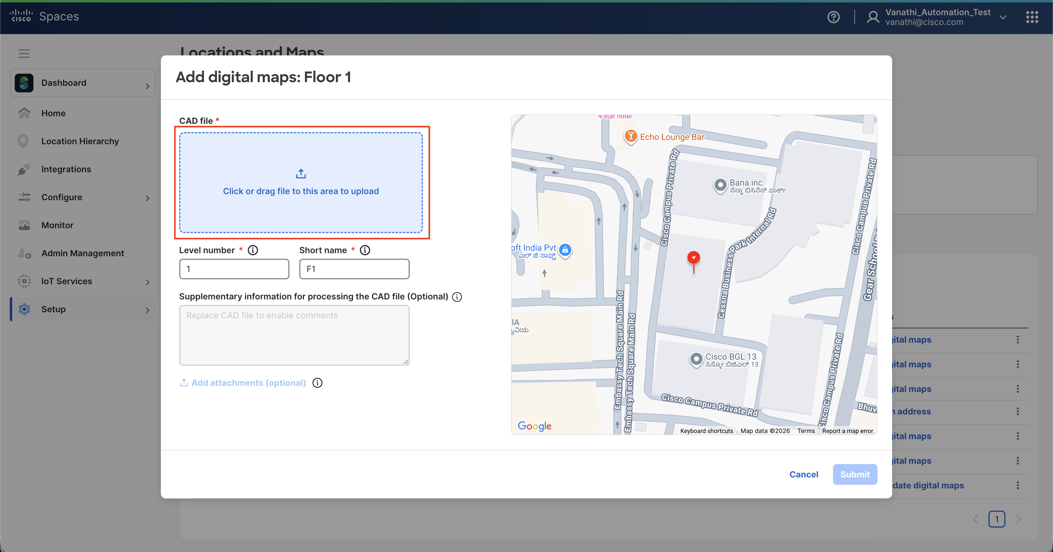
STEP 7: Upload the CAD/Vectorized pdf file.
Click or drag file here to upload.
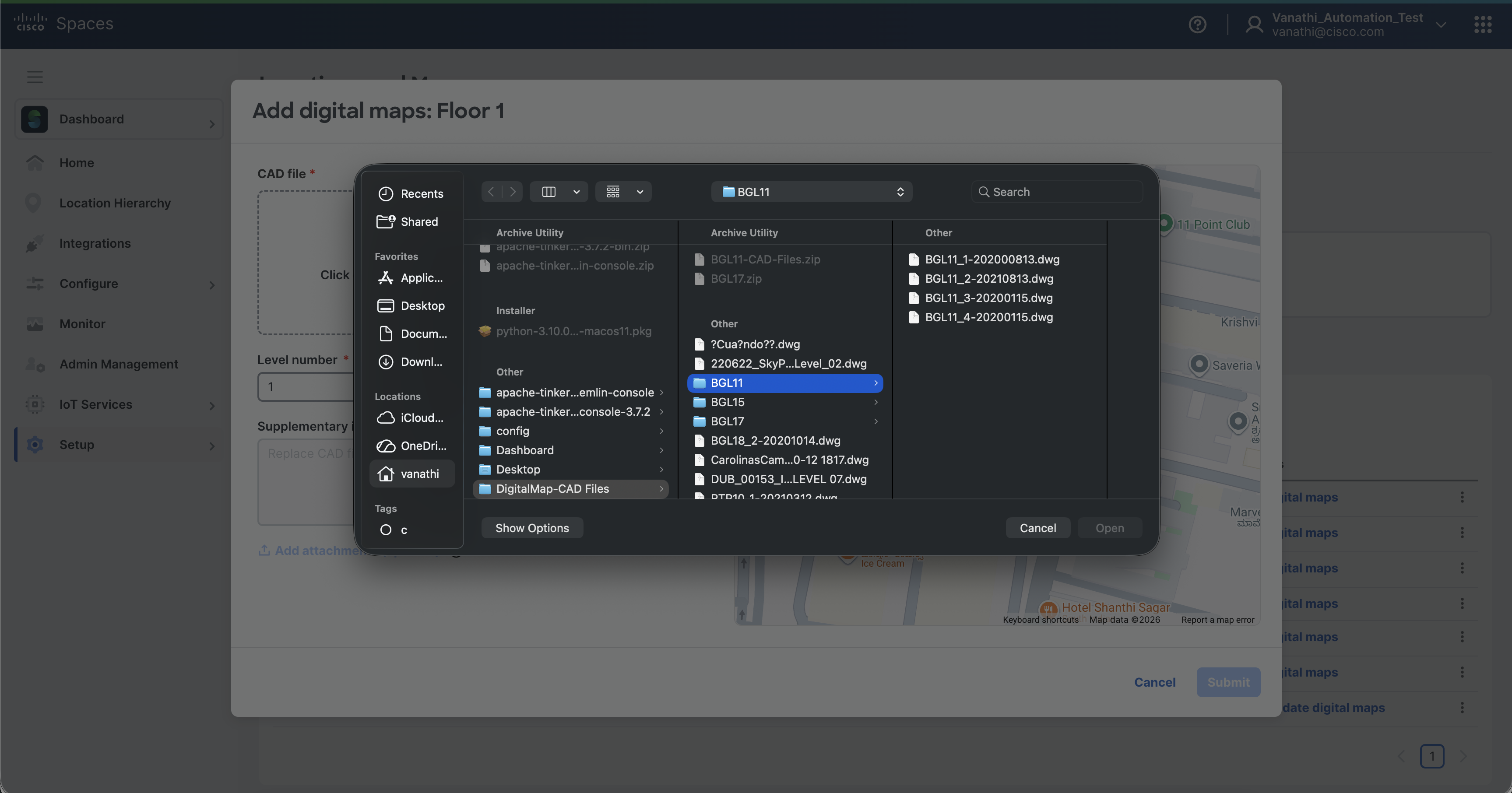
Edit the floor details if incorrect and add supplementary information for processing the CAD file.
Hidden and “frozen” layers will not be processed. Missing objects will need to be un-hidden or un-frozen, and re-uploaded to be processed correctly. Cross Reference (XREF) files are not supported. If your CAD files include XREF, first merge them into a single DWG, then upload.
Select the file from your device and click the Submit button.
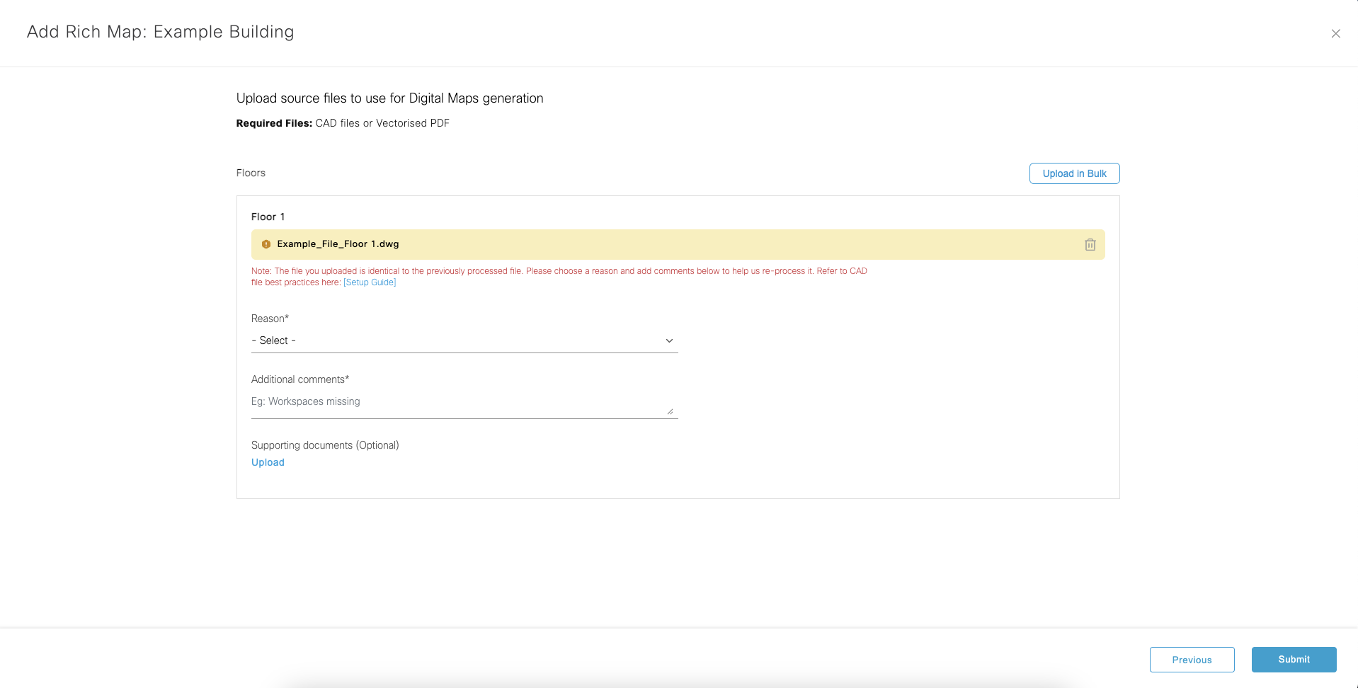
An additional dropdown and input fields will appear if the selected file is already submitted for another building in this account. You must select the Reason for force submission and provide Supplementary information for processing the CAD file before the submission.
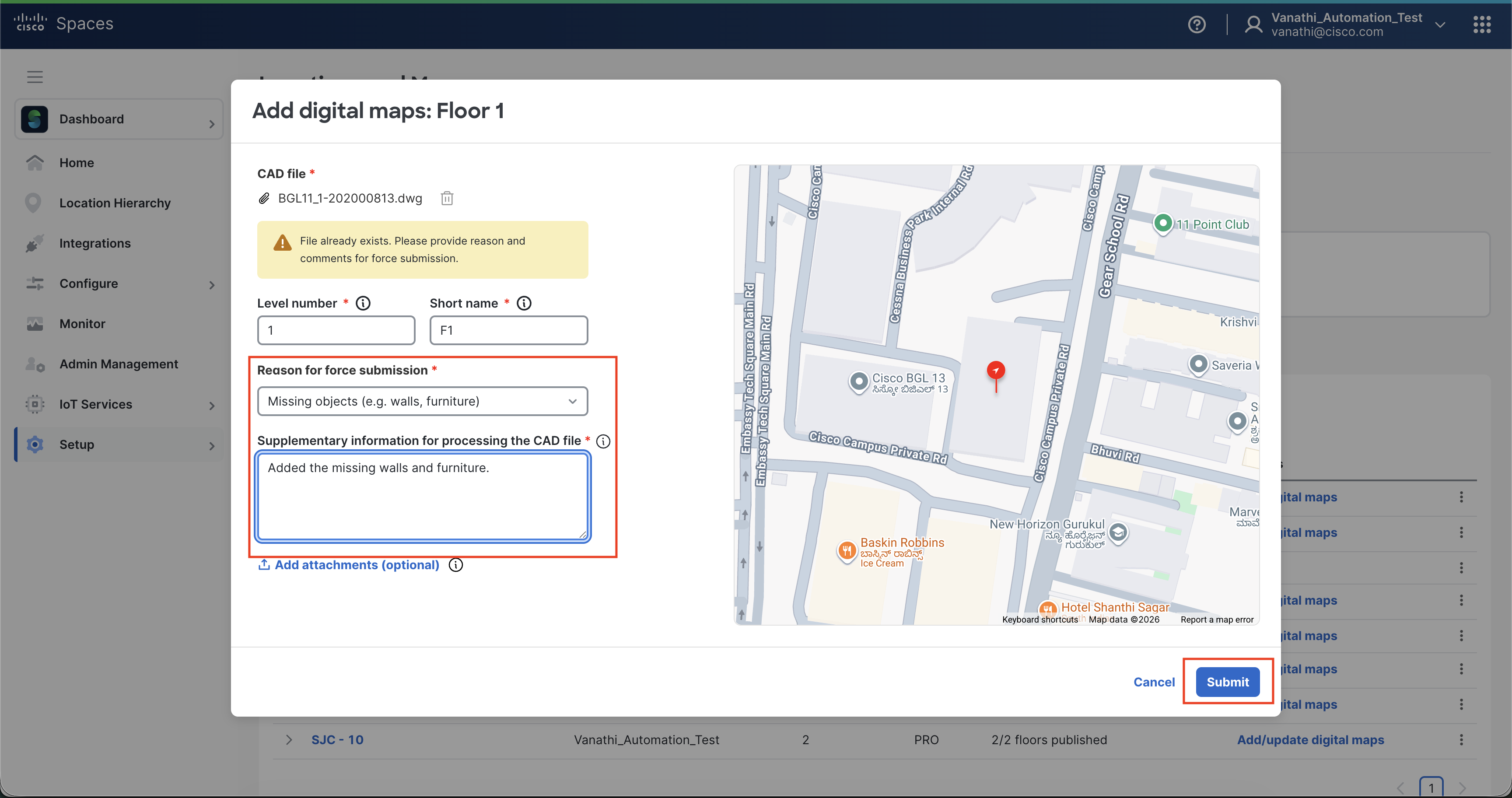
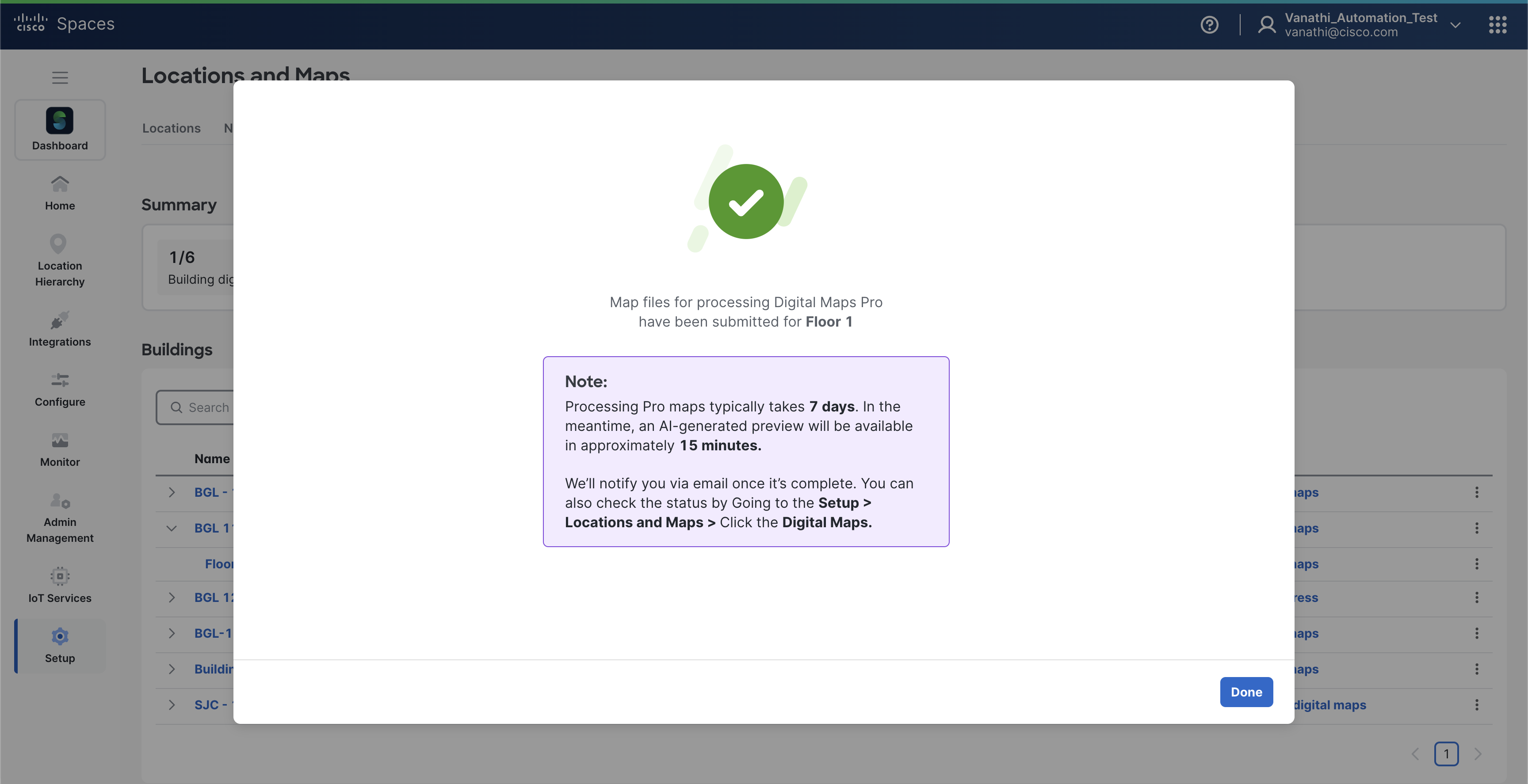
Your CAD file submitted for Digital Maps processing, an AI-generated preview will be available in approximately 15 minutes. You will receive an email notifying that the AI Preview is available to review.
This is a great opportunity to review the content of the CAD file, but missing elements or incorrect space names may be incorrect. The Cisco Spaces Mapping Team will review and provide a final corrected version that will be editable (see STEP 8 below). In most cases, metadata or structural elements the AI did not capture correctly can be corrected in the QA phase of processing. If the Cisco Spaces Mapping Team determines that there is important missing information, the CAD files will be rejected with a reason and notes for corrective actions.
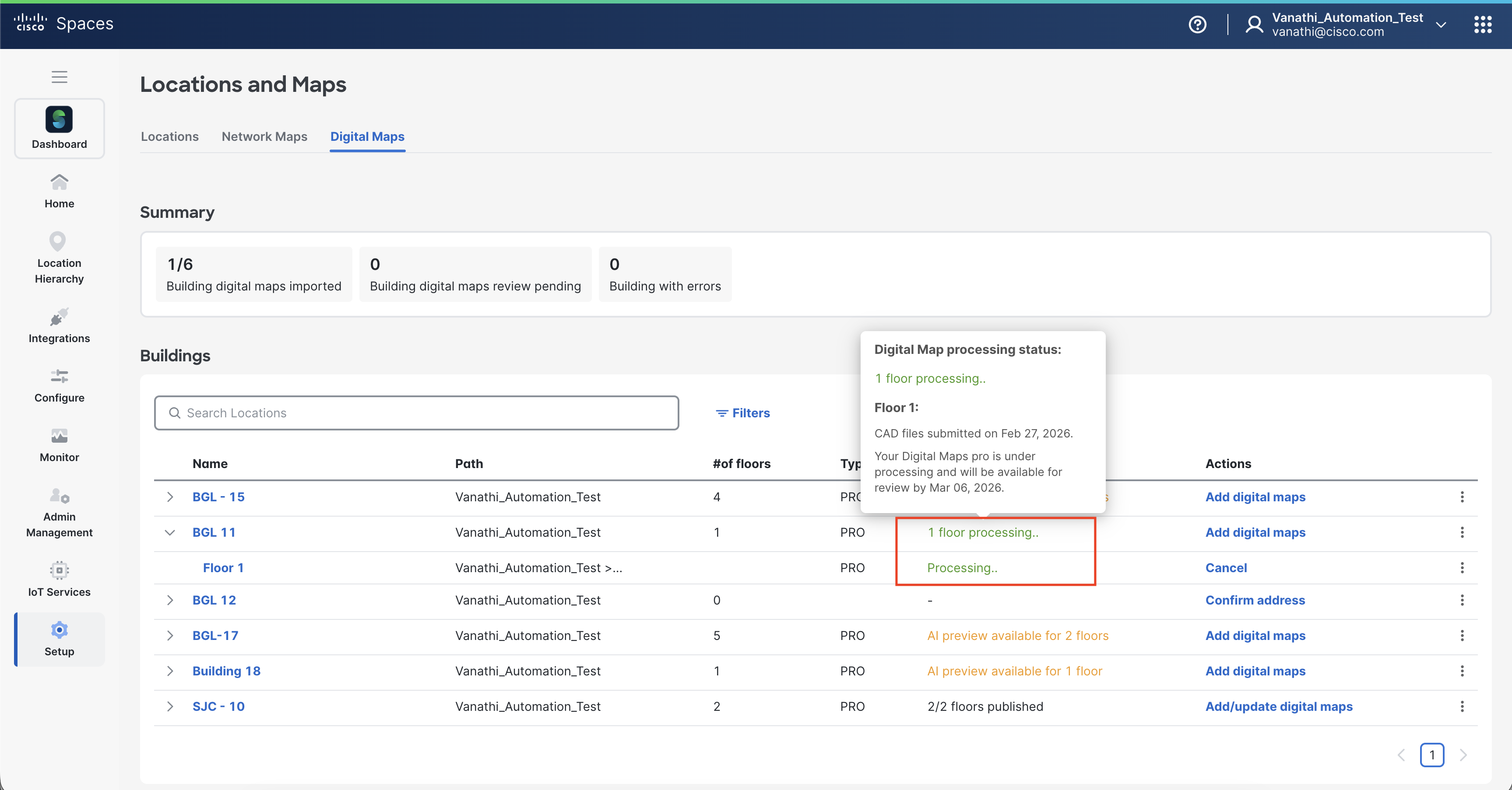
STEP 8: The map status is now Processing. The list view will display the status as Processing.
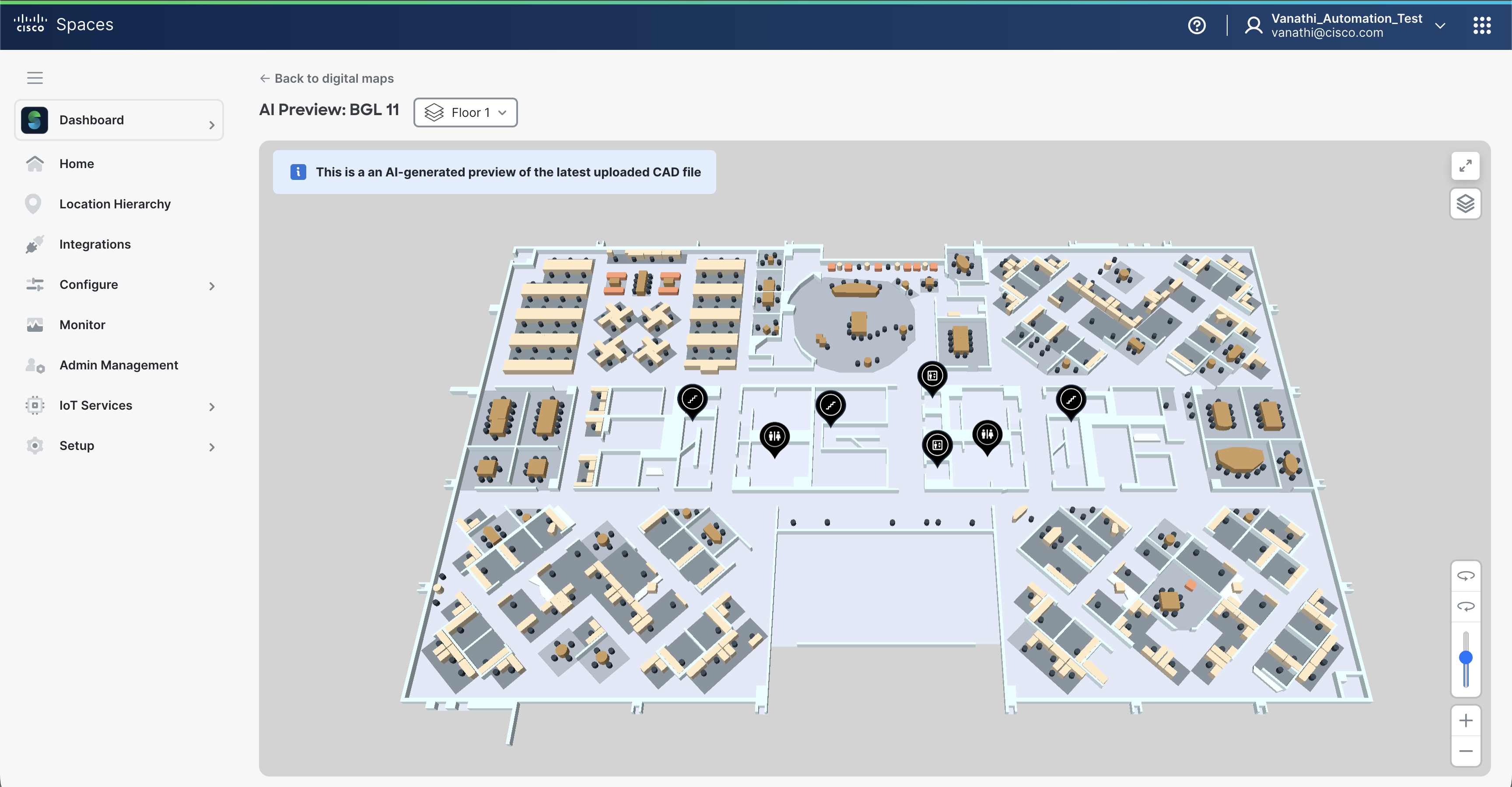
STEP 9: When the AI-generated preview appears, click View to display the AI preview
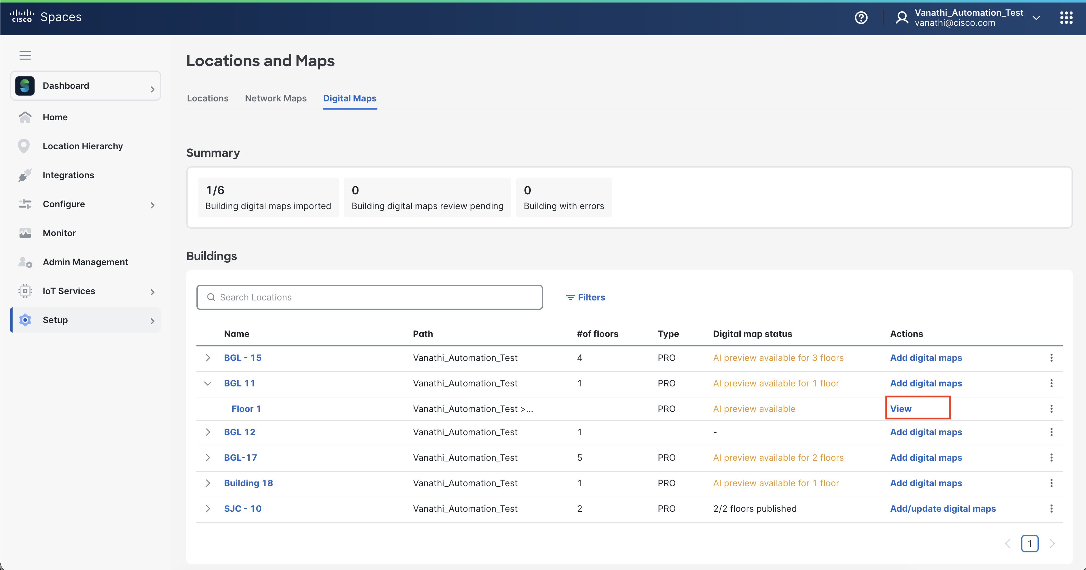
Sample preview of your map.
You cannot edit this map until your Digital Map is ready for review.
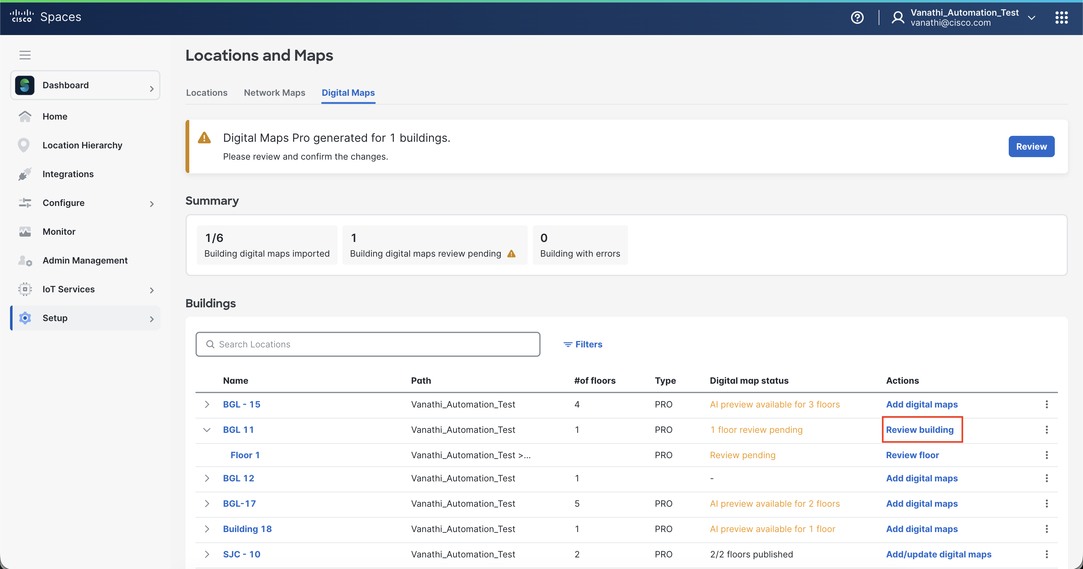
STEP 10: Once processed, Processing Status will change to ‘Review pending’. Click “Review building” or “Review floor” to view the processed Digital Maps.
STEP 11: Review building - Review all floors at once.
Add/Edit Room Labels. Once everything looks good, select “Publish”.
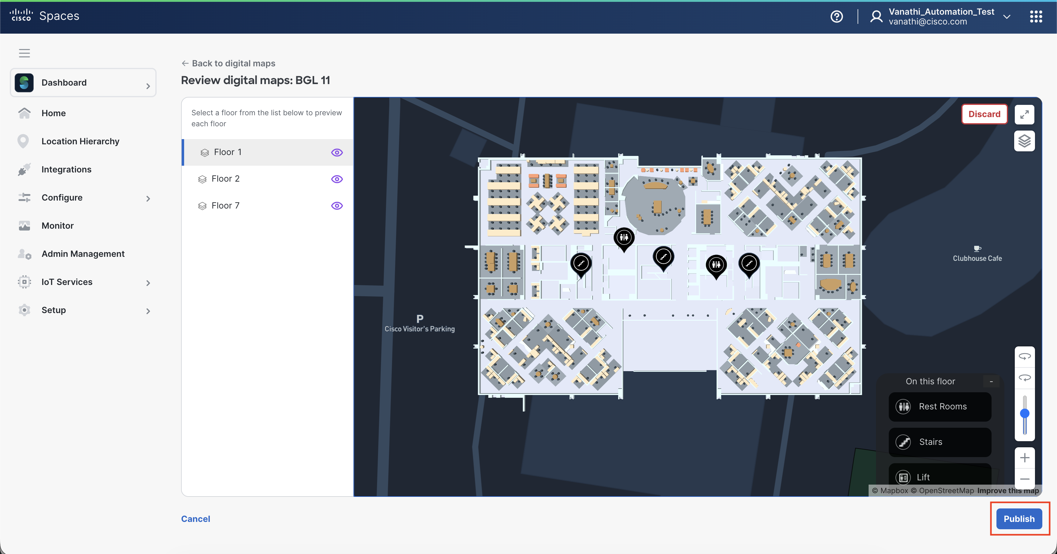
Review floor: Review one floor at a time.
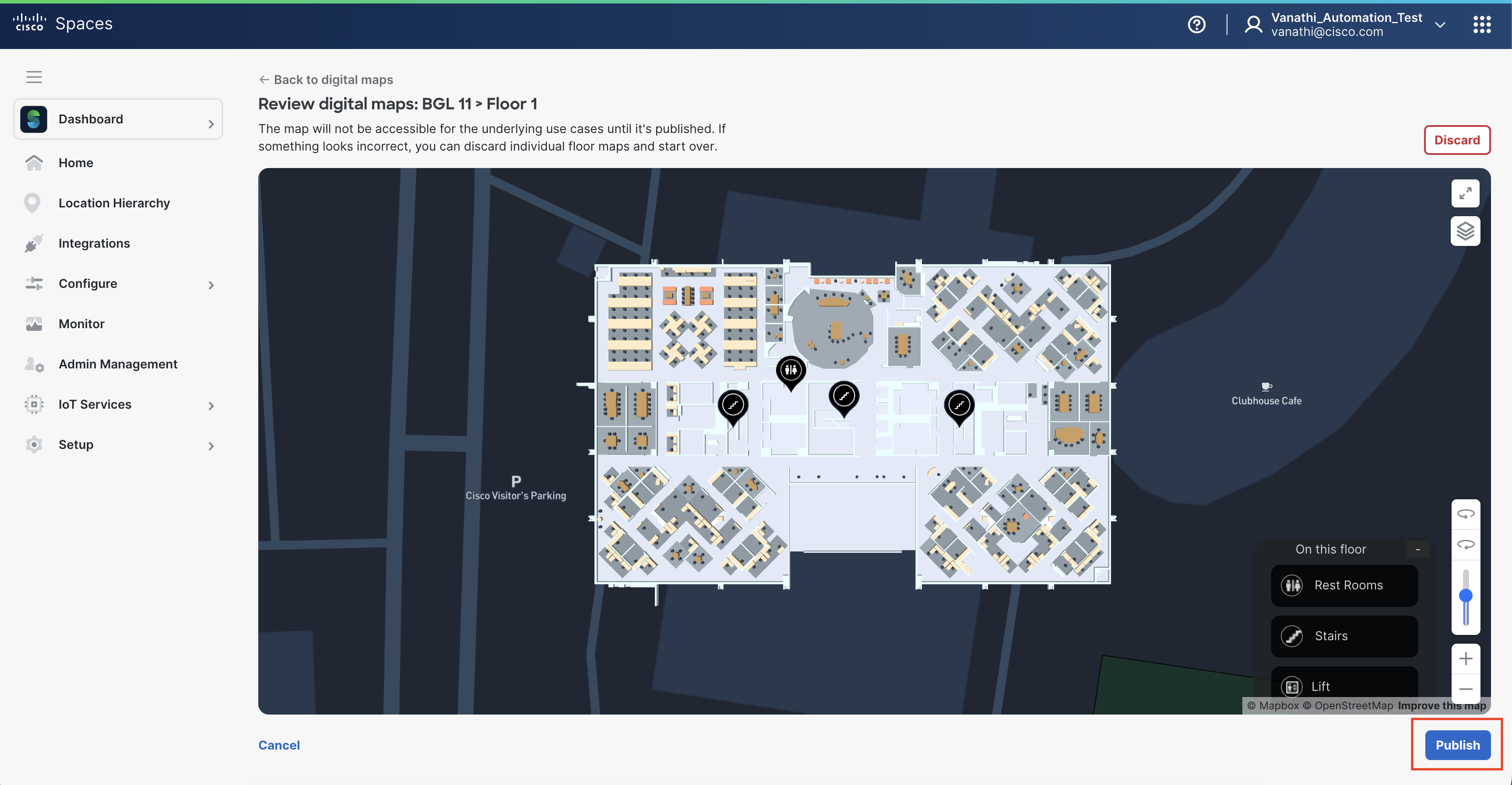
STEP 12: The Digital Map is now published successfully
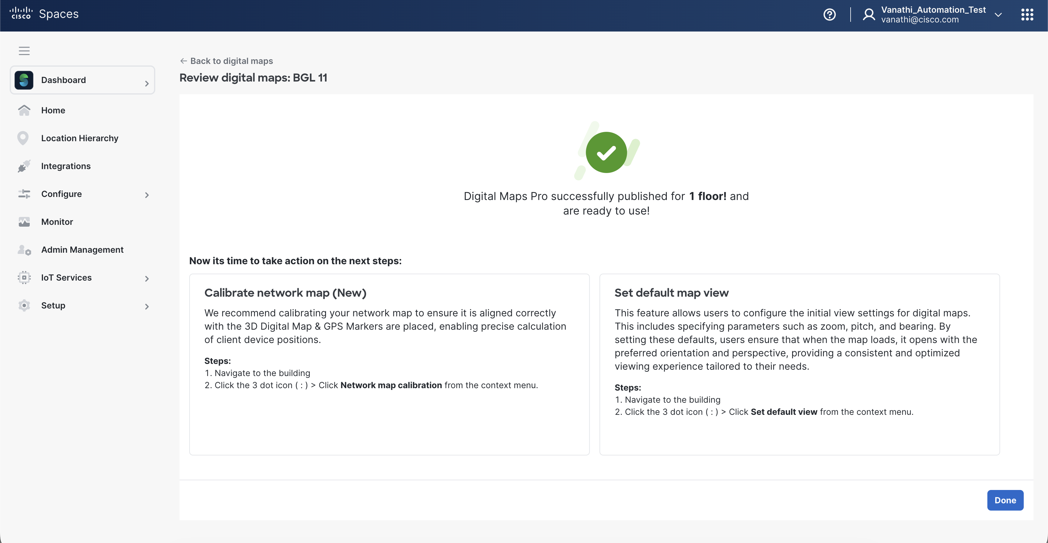
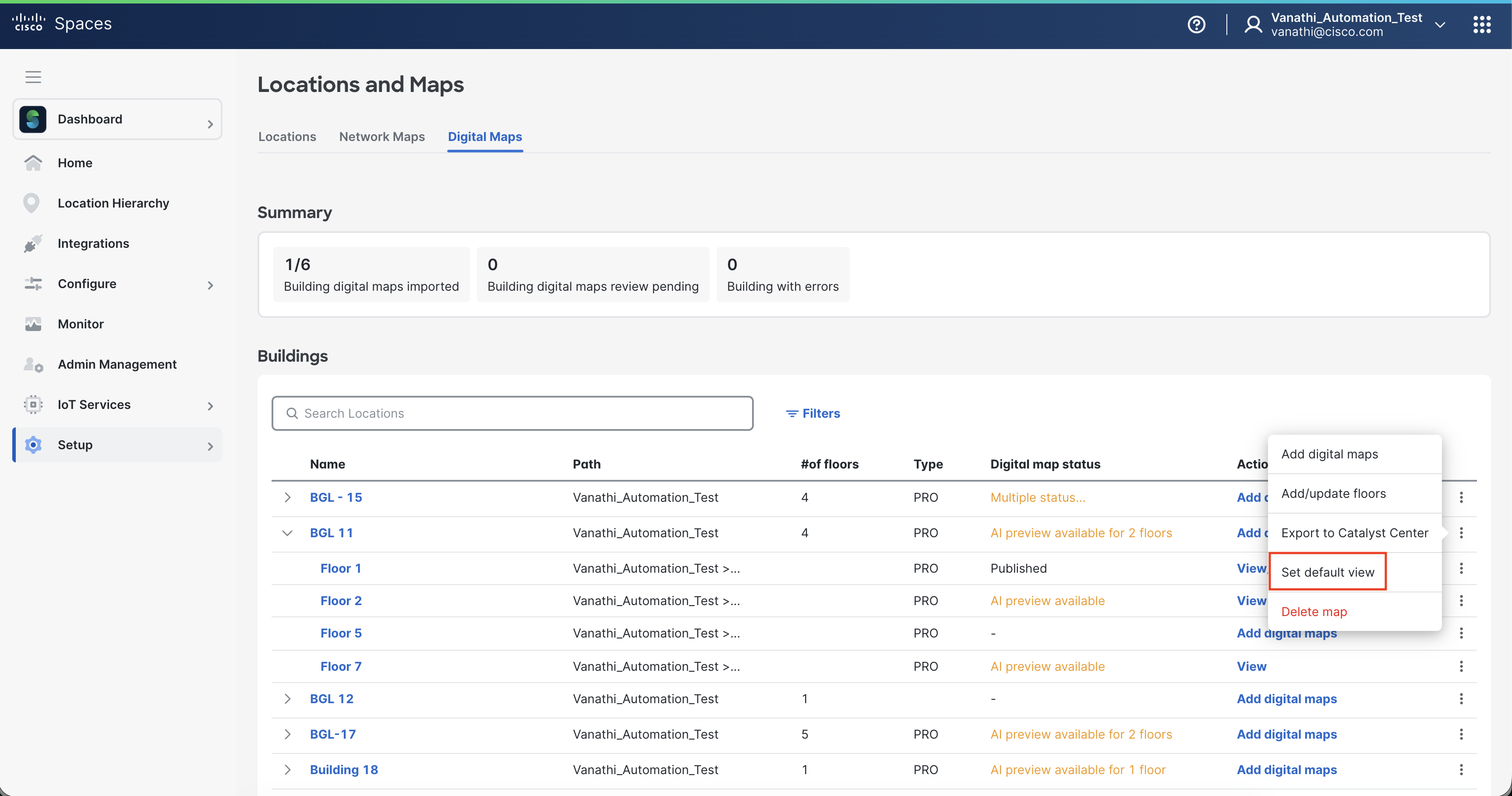
STEP 13: You can set the default map view for the published maps.
Click on “Set default view” against the building.
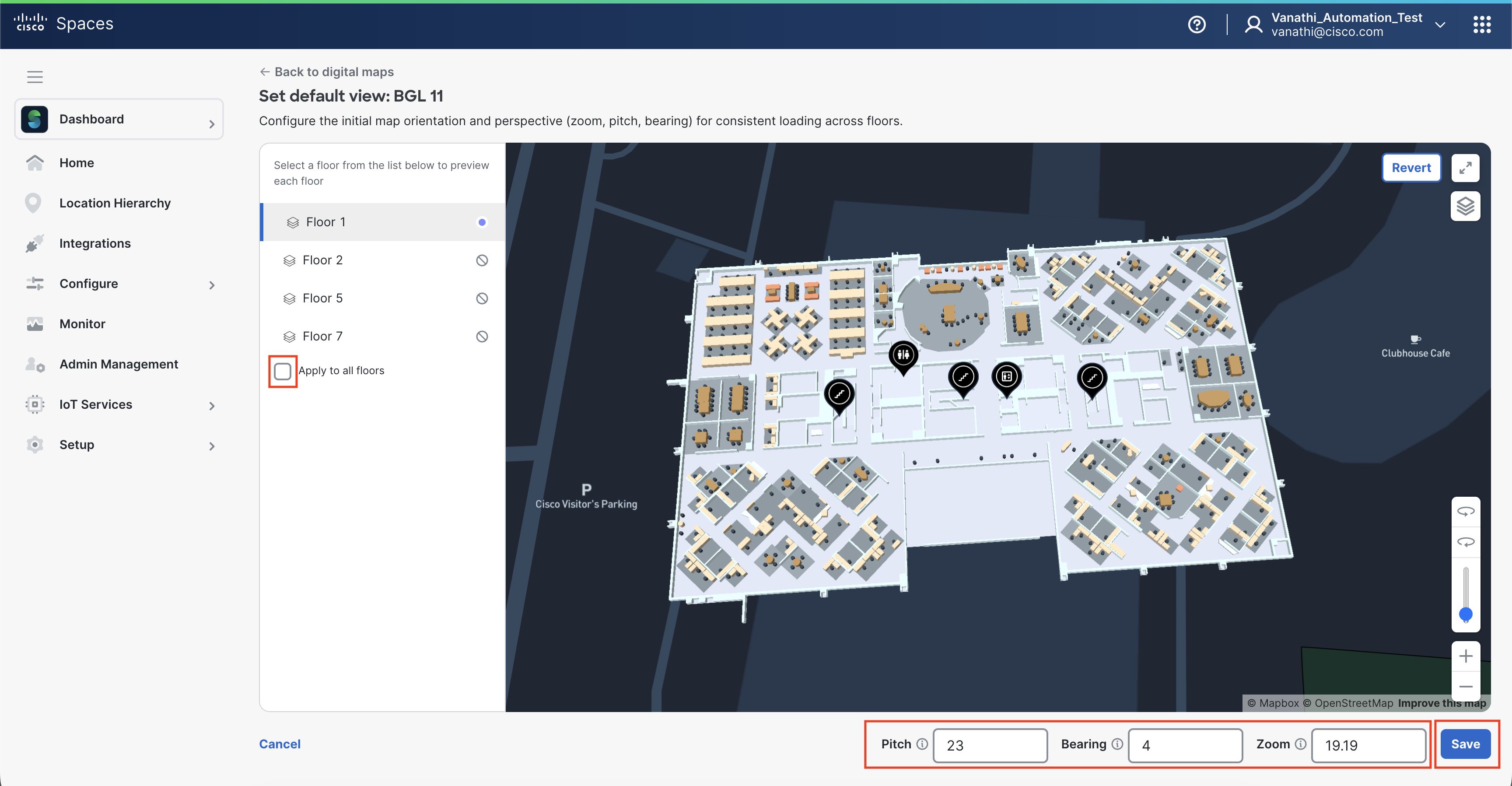
STEP 14: Adjust the map's center, pitch, bearing, and zoom, then save to set the default view. Use the "Apply to all floors" option to apply these settings across all floors if desired.
Changes on each floor save together when you click Save. Updates apply only after editing all floors and saving once.
STEP 15: Click “Network map calibration” for the selected floor.
Network map calibration
We recommend calibrating your network map to ensure it is aligned correctly with the Digital Map & GPS Markers are placed, enabling precise calculation of client device positions. Learn more: https://runbooks.ciscospaces.io/docs/guide-to-network-map-geo-placement-and-best-practi
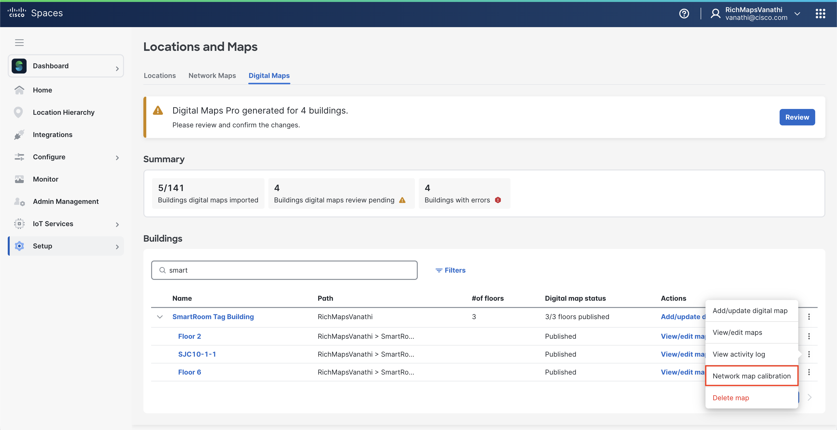
STEP 16: Roughly align the network and Digital Map layers to match to map orientation (does not need to be precise in this step), then click the “Next” button.
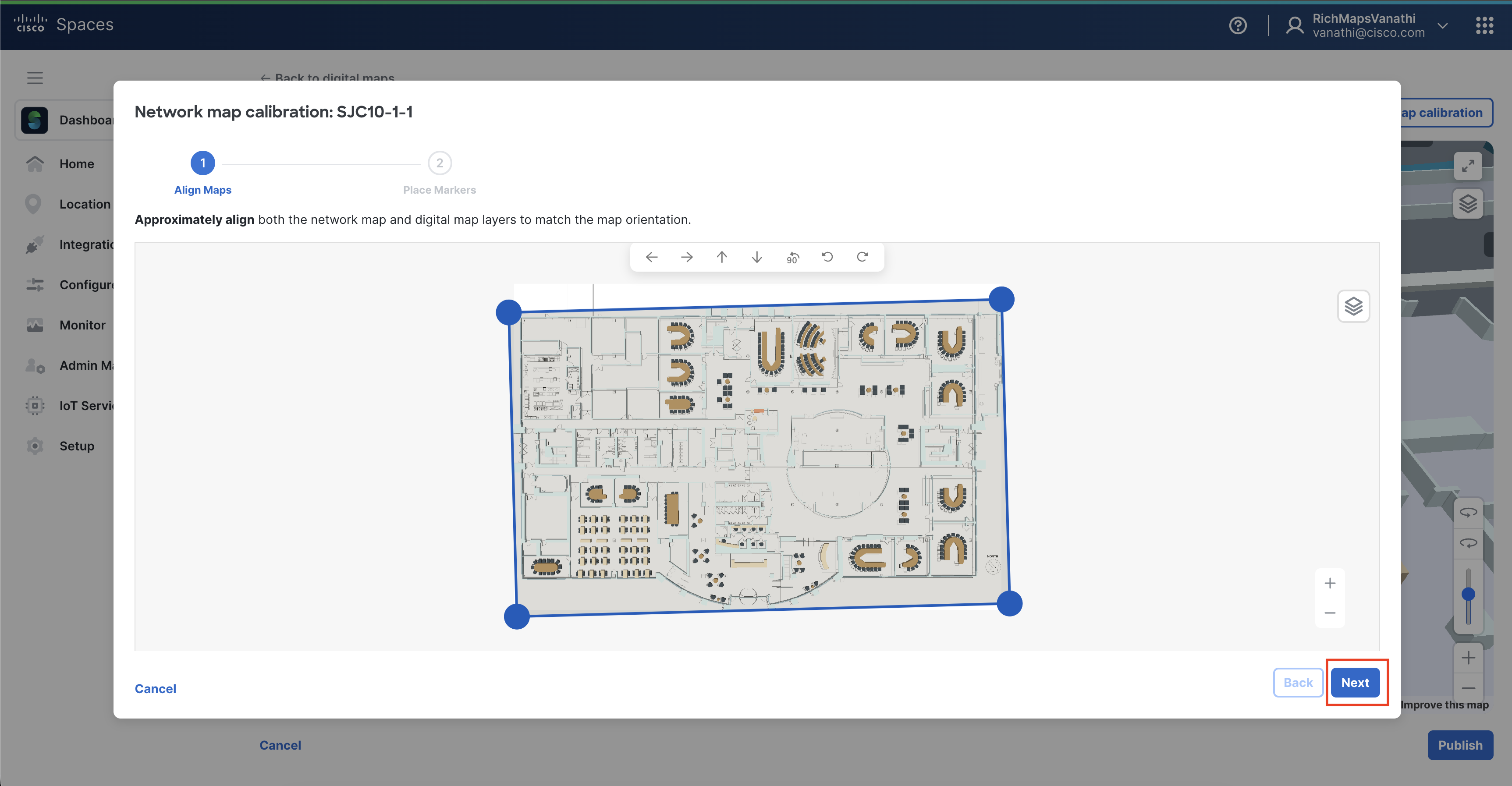
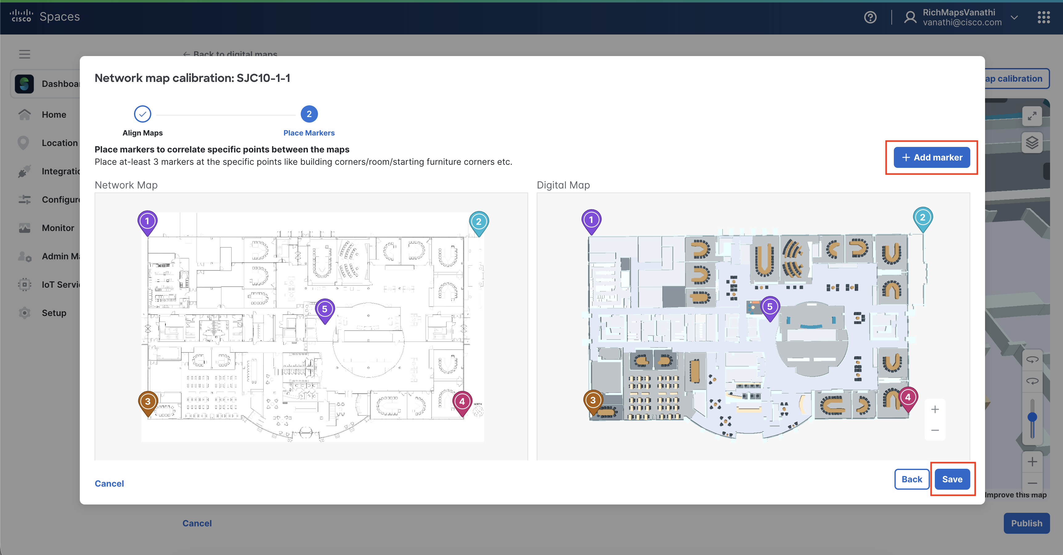
STEP 17: Click “Add markers” to place markers correlating specific points between maps, which must be exact. Then click the “Save” button to save alignments and markers.
Place at-least 3 markers at the specific points like building corners/room/starting furniture corners etc.
Delete, discard or cancel Digital Maps
Delete Digital Map
Delete Digital Map
STEP 1: Click on Delete map to remove all map versions under the building, including unpublished and published ones. This action may affect linked configurations such as Kiosks, Wayfinding, Occupancy tracking and devices on the map.
Warning: DO NOT delete Digital Maps in order to process an updated floor file. Under Setup > Locations & Maps > Digital Maps > “3 dots” menu on the location/floor list item, you can Add Digital Map to replace the existing Digital Map. The workflow is the same as initially uploading, but after processing, previous Digital Map content will be preserved if there were no structural or name/ID changes to the individual spaces/POIs. This ensure data and device assignment continuity between uploads, while only processing the differences between the CAD file versions uploaded. Deleting the Digital Map erases all database records and cannot be reversed.
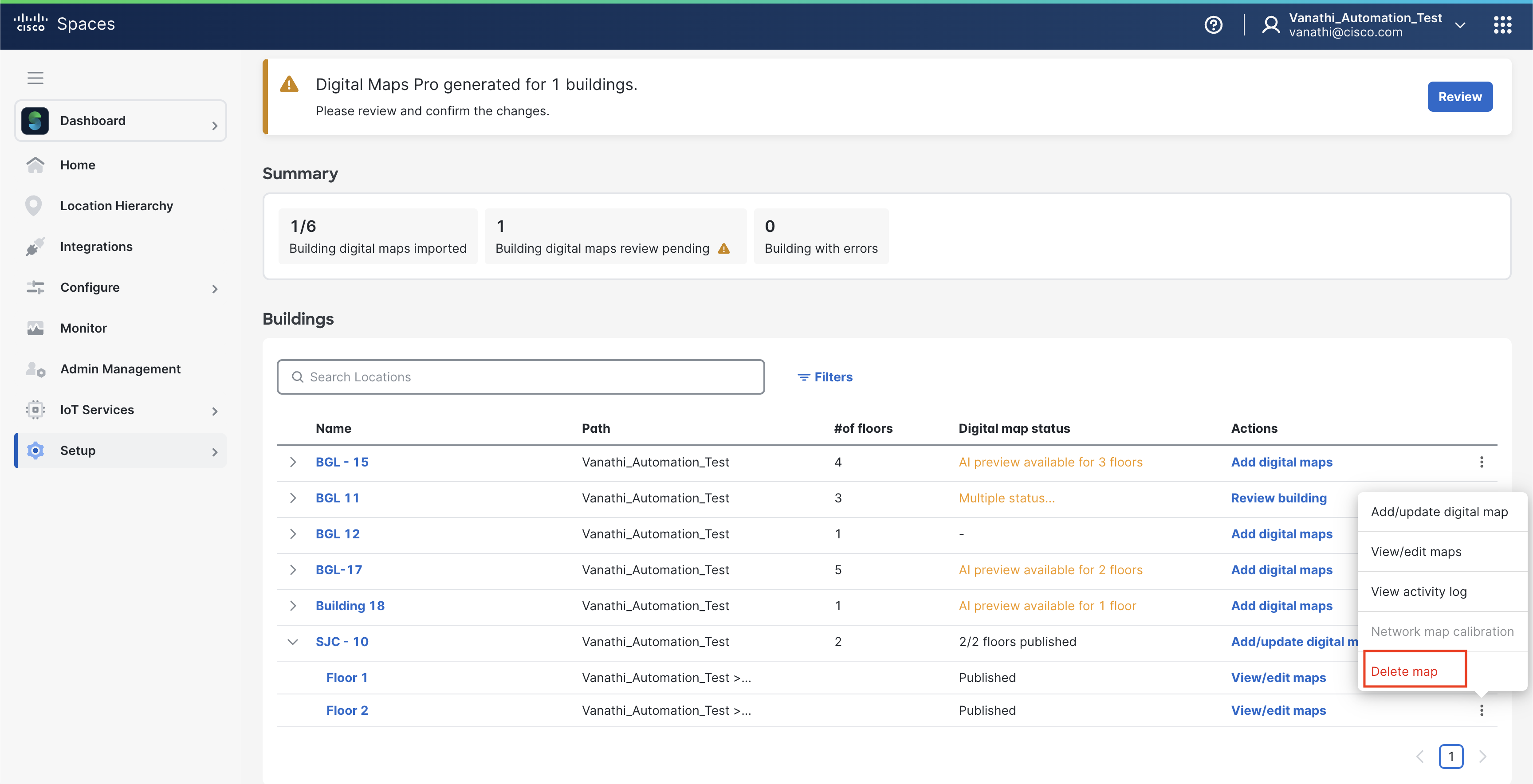
STEP 2: Enter all required inputs, including the reason for deletion and additional comments, to confirm the action. Deletion is irreversible.
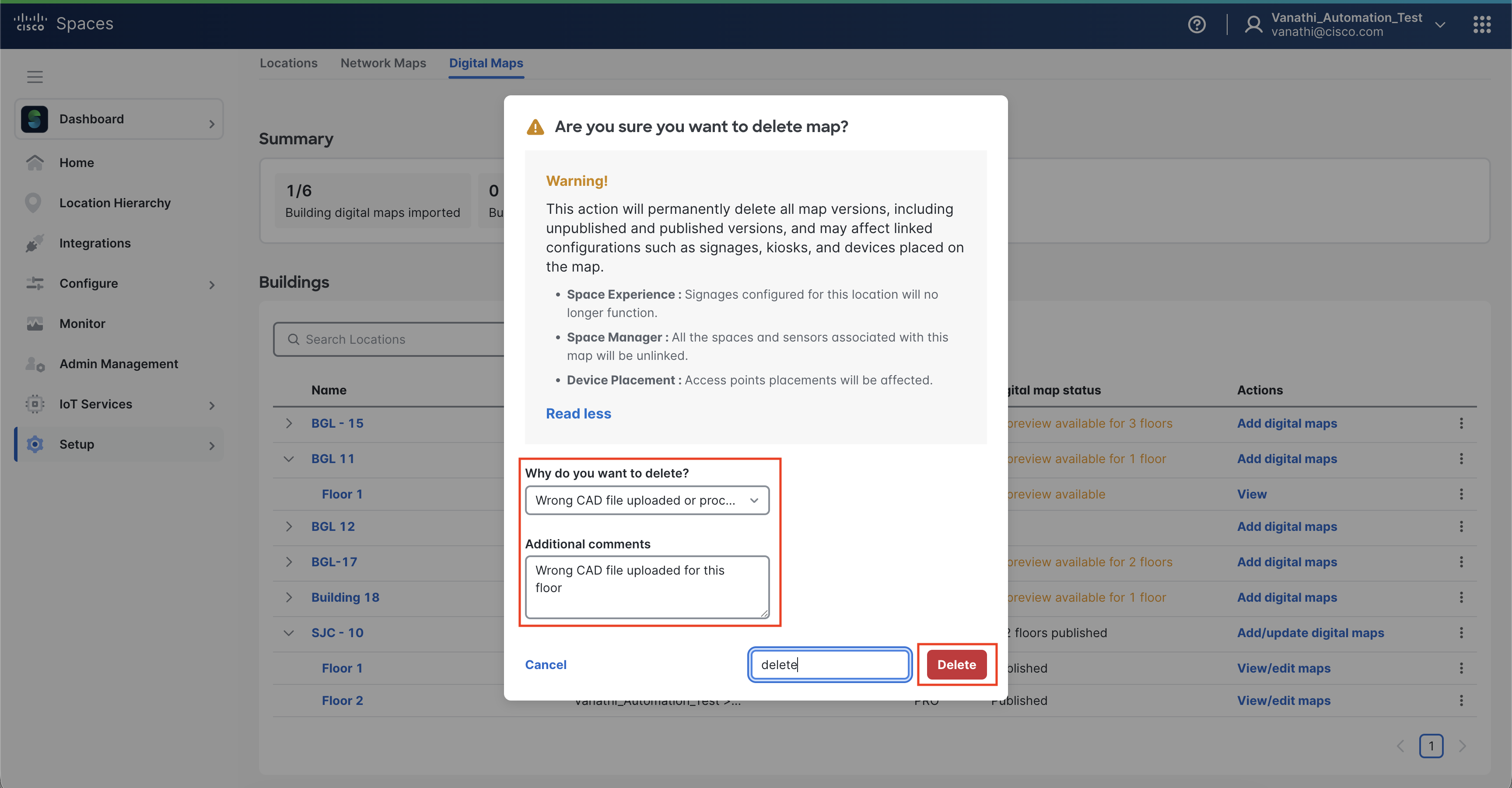
STEP 3: After deleting all the maps, you can upload a CAD file or Vector PDF to create a new Digital Map if needed.
Discard Digital Map
Discard Digital Map
If something appears incorrect, discard individual floor maps that have been processed but not published, then start over.
Note: Discarding is ideal for fully processed Digital Maps that are obviously incorrect floors or missing elements that you believe are caused by a bad CAD file.
STEP 1: Click “Discard map” next to the floor whose processed maps you want to discard.
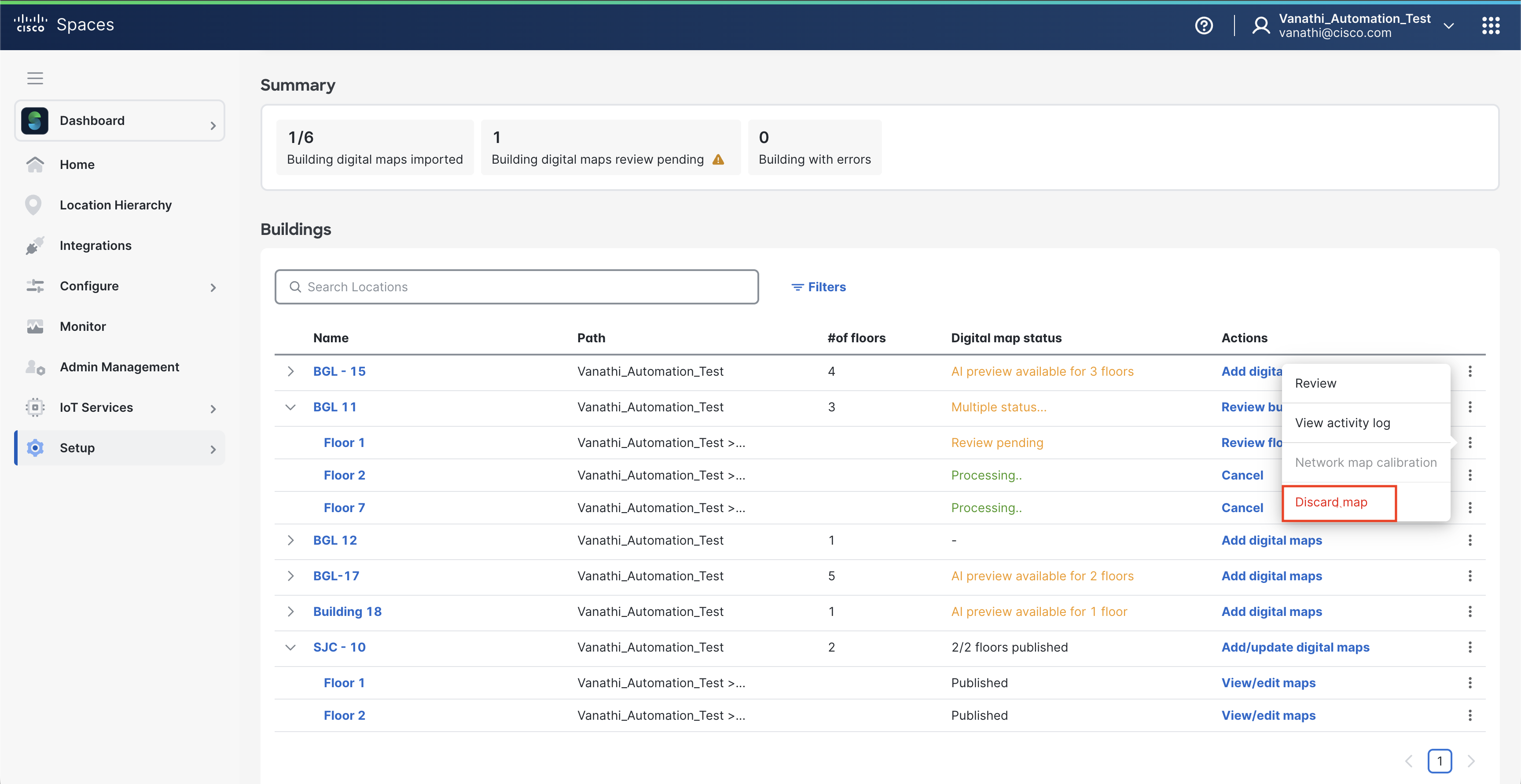
STEP 2: Enter all required inputs, including the discard reason and additional comments, to confirm. Discarding is irreversible.
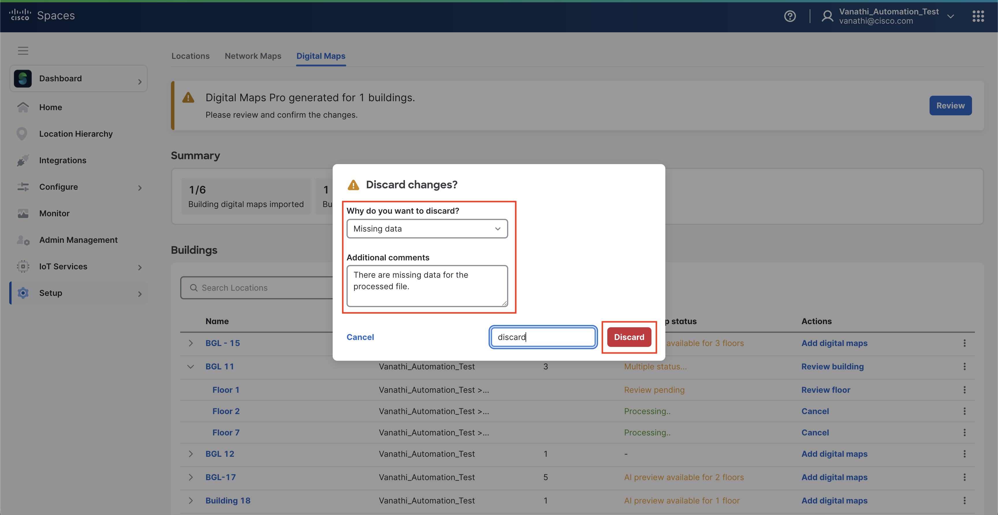
STEP 3: After discarding all the maps, you can upload a CAD file or Vector PDF to create a new Digital Map if needed.
Cancel Digital Map
Cancel Digital Map
You can cancel the maps which are in progress / under processing or AI generated preview maps.
Note: Canceling is ideal for AI Preview that are obviously incorrect floors or missing elements that you believe are caused by a bad CAD file. It is possible the AI output can be corrected by the Cisco Spaces Mapping Team, but if not, they will add a note when rejecting during QA.
STEP 1: Click “Cancel” to stop processing the Digital Maps.
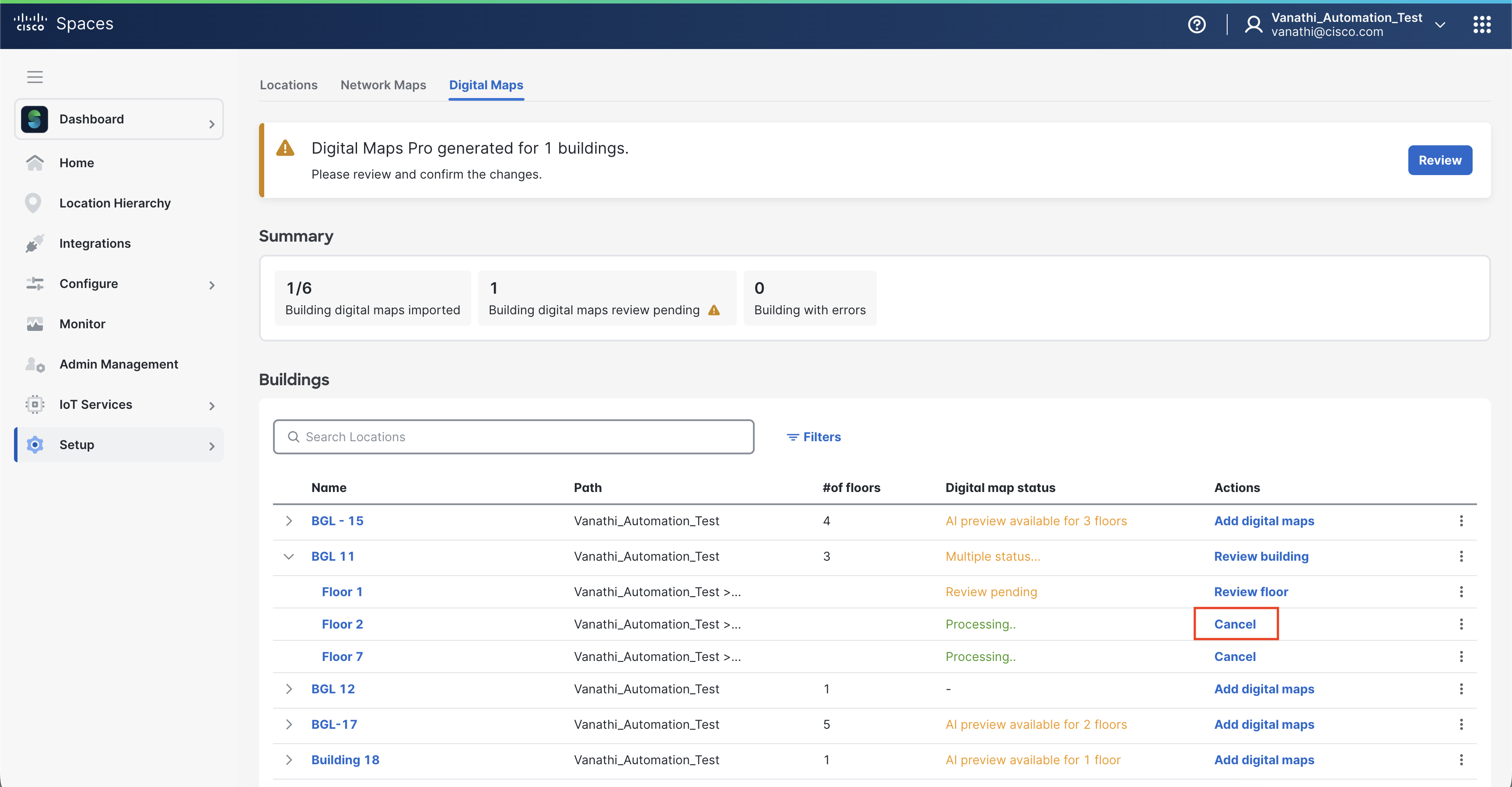
STEP 2: Enter all required inputs, including the reason for cancelling and additional comments, to confirm. Cancelling is irreversible.
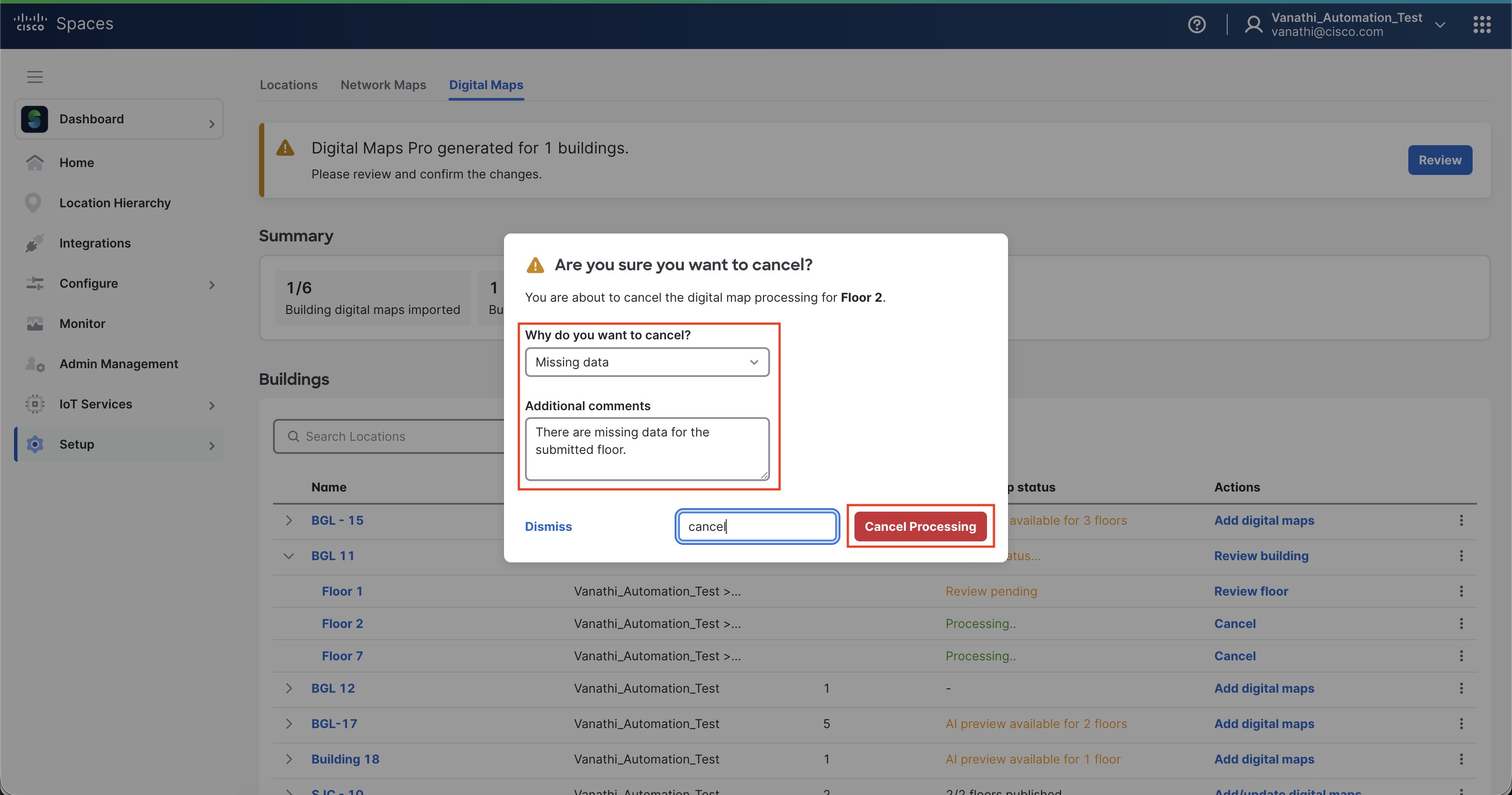
STEP 3: After cancelling all the maps, you can upload a CAD file or Vector PDF to create a new Digital Map if needed.
Enabling IoT Services

Now all infrastructure and hierarchy is set up and Digital Maps created, IOT Services can be enabled. IOT Services gives Cisco Spaces the functionality to scan and transmit using the BLE radio.
Catalyst Deployments
Catalyst Deployment
In this section, we will enable IOT Services for Catalyst based deployments. To do this, we will enabled IOT Services on Spaces Connector, then WLC, then required APs.
IOT Services Wizard flow (prefered)
-
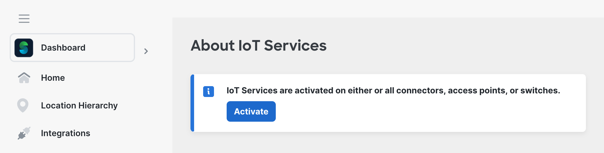
Navigate to IoT Services > About and click the Activate button. The About IoT Services window will open.
-
Ensure that Wireless is selected and click Next.
-
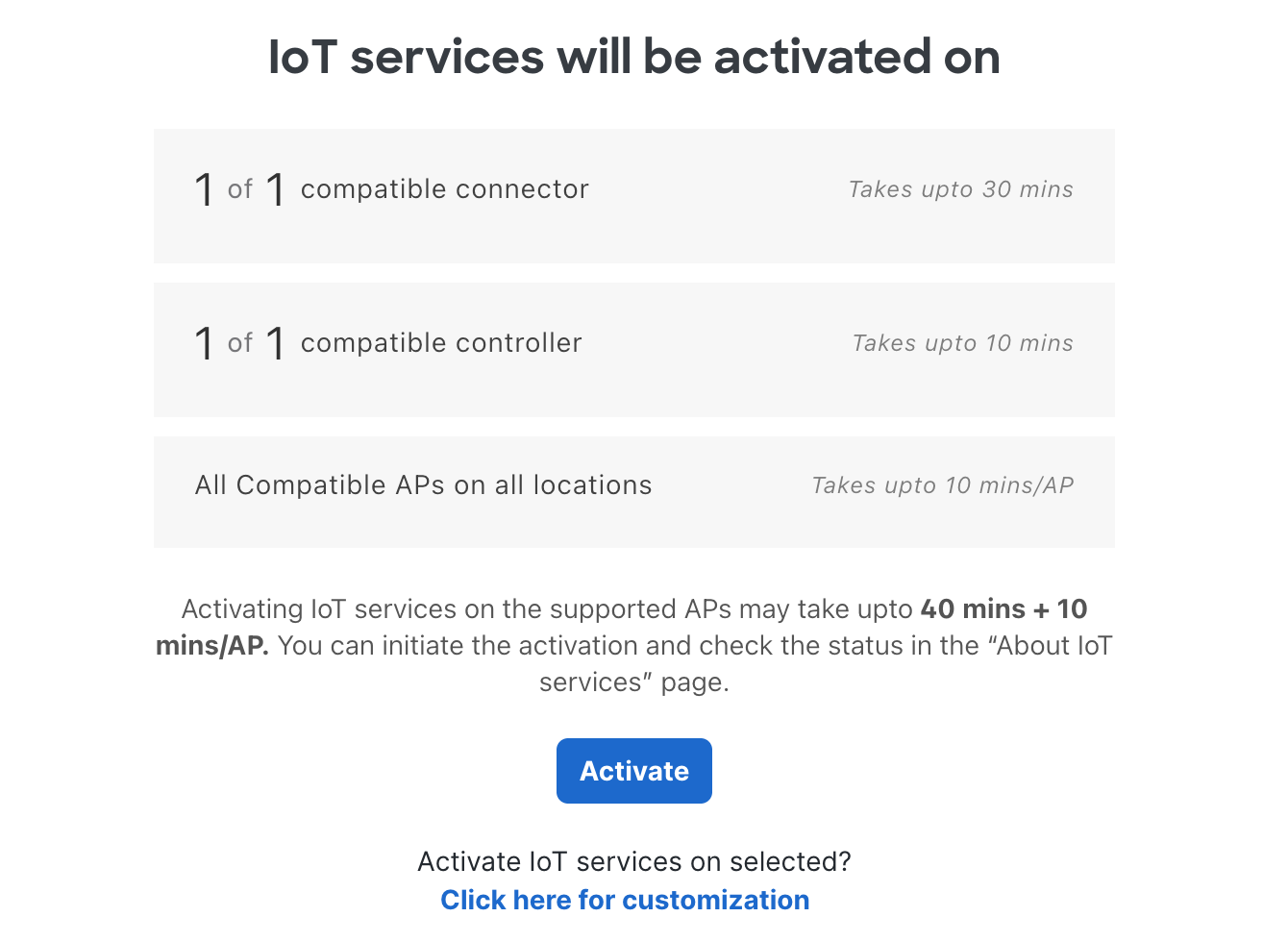
The prerequisites will be checked automatically. If any of the prerequisites are not met, resolve this before continuing. Once complete, the IoT Services Activation page will open.
-
By default all compatible connectors, controllers and APs will be enabled for IoT Services. To proceed with this, click Activate.
-
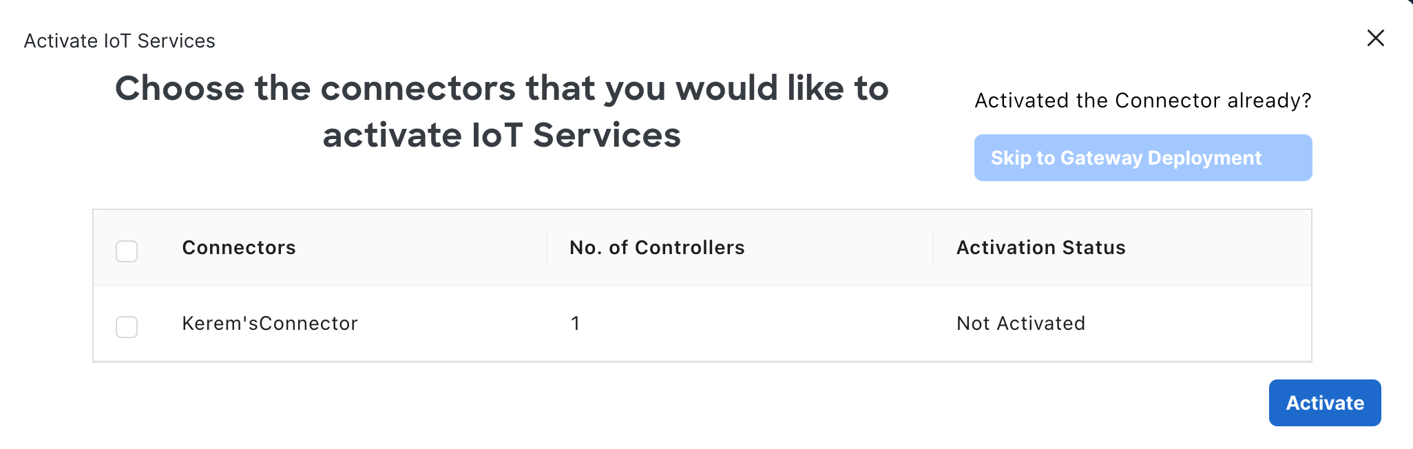
To customize which connectors and/or APs to deploy IoT Services to, click Click here for customization.
-
Select the connector(s) where IoT Services will be deployed to and click Activate.
-
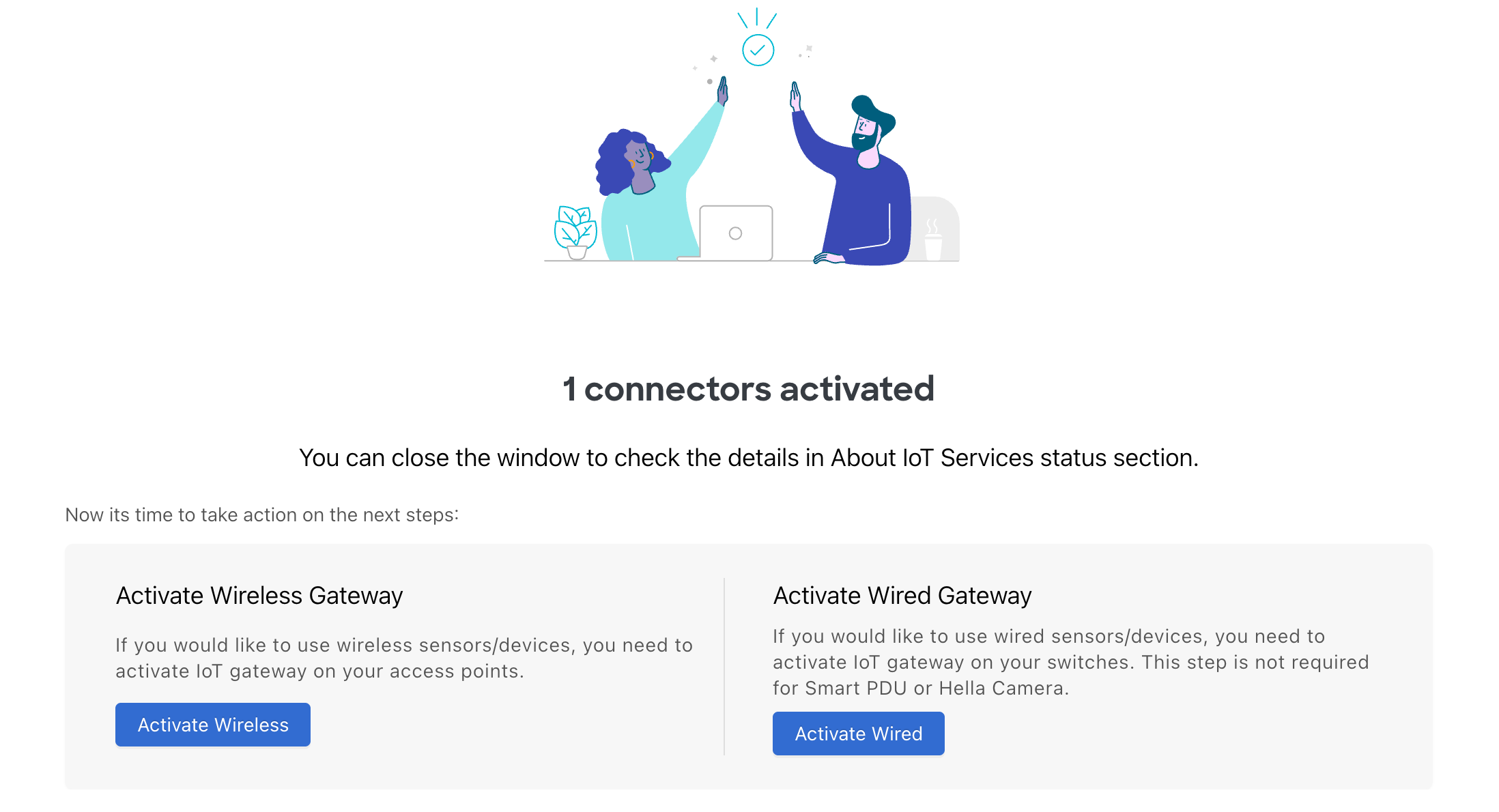
Wait for the connector(s) to be activated, then select Activate Wireless.
-
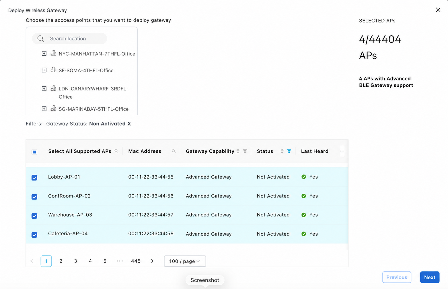
Select all APs required to deploy IoT Services, then select Next and then Activate.
-
-
Activation is now underway. Use the menu under IoT Services > About > View Detailed Status to monitor the status of IoT Services.
Use this Deployment Status page to help monitor IoT Services status on a regular basis.
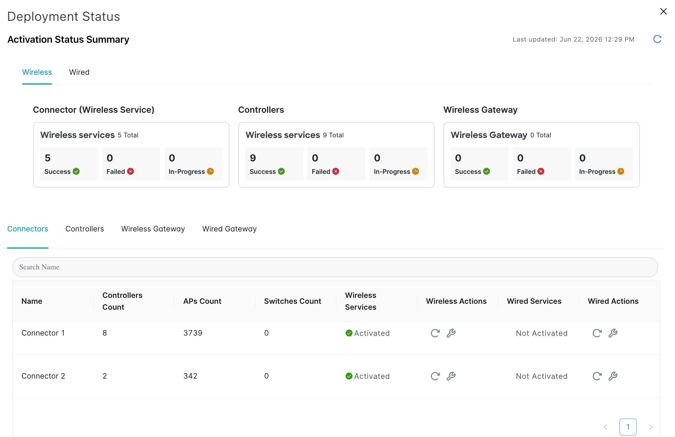
The activation process will be completed when all of the In-Progress deployments, are shown as Success.
Investigate any failed deployments and reactivate the IoT Services.
IOT Services Manual Enablement
Spaces Connector
First, we must enable the IOT Services functionality on the connector. This creates a new container on the connector, pushed through Spaces dashboard.
Installing the IoT Wireless container will automatically enable IoT Services for all associated WLCs. This includes pushing configuration to WLCs
-
Log into Cisco Spaces and head to Setup > Wireless Networks.
-
In the Connect via Spaces Connector section, click on View Connectors, and open the connector you want to deploy IOT Services to.
-
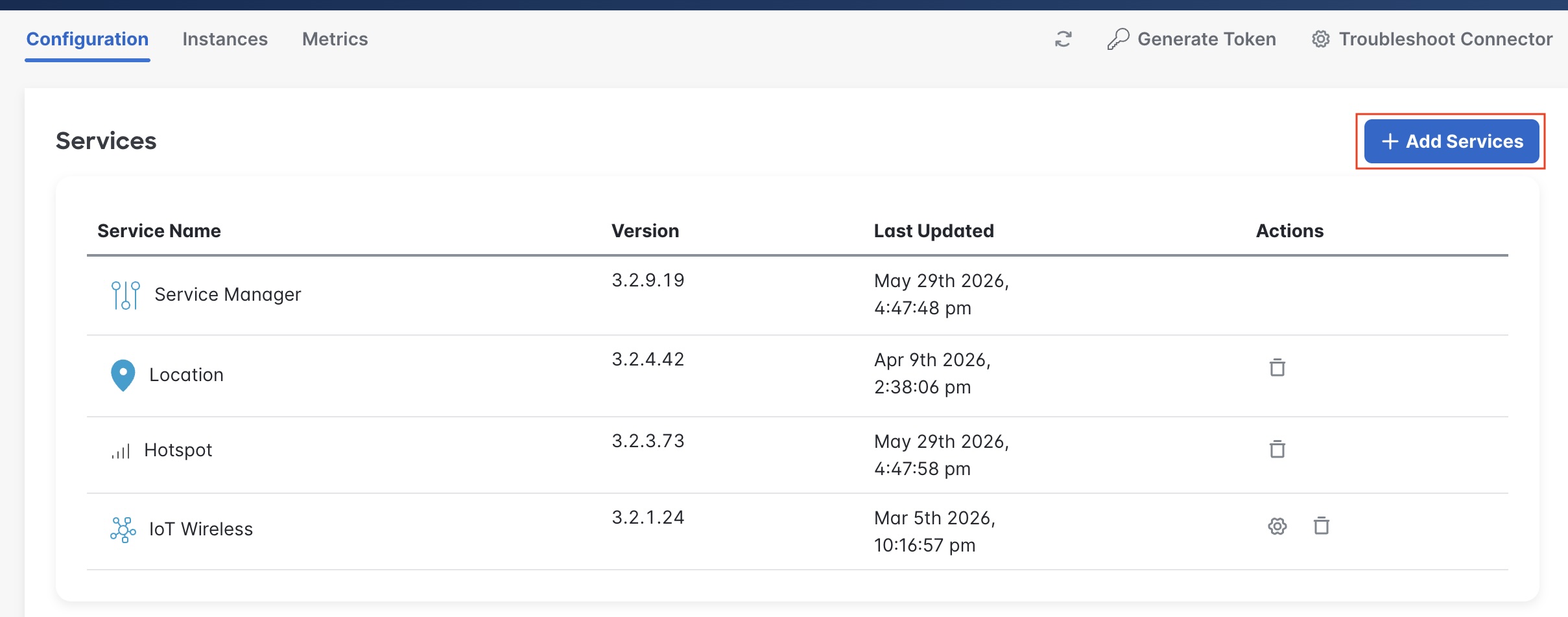
Click on + Add Services, select IoT Wireless, then click Save.
This will begin the install of the IoT Wireless container onto the chosen connector. This will take 5 minutes or more, and will go through the stages of; Queued → In Progress → Complete.
WLC
As mentioned above, enabling IOT Services on Spaces Connector will automatically try to configure IOT Services on the WLC as well. This section will validate this has been completed, and work through common issues seen.
-
Under Setup > Wireless Networks > View Connector, open the required connector, and click the cog icon under the actions menu.
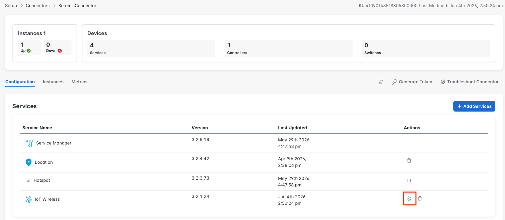
-
You will then be shown a list of associated WLCs for this connector, as well as the status of IOT Services configuration for each. We are looking for all WLCs to say SUCCESS.
APs
We have now enabled IOT Services on the required WLC and Connector. In this step we will enable IOT Services on the required Access Points.
Deploying IOT Services to Access Points, should not impact client serving ability of the AP, but there have been occurrences that this has happened. Reccomendation is to deploy during times of low traffic, or outage windows.
-
IOT Services > Manage, and navigate to the building you wish to deploy IOT Services to.
-
Use the checkboxes, to select required APs to deploy IOT Services to.
-
Select from the top bar Action > Manage IOx App > Install IOx App.
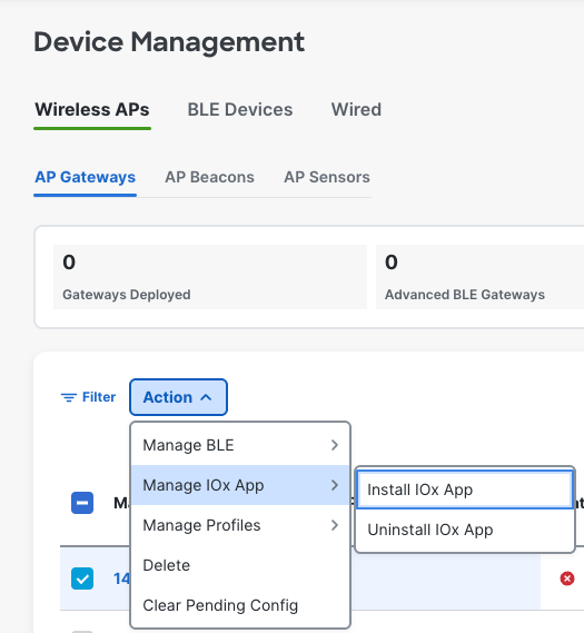
-
The Bulk IoX App Management panel will then appear. Click Install, then Confirm. This will then proceed to install IOT Services for each of the selected APs.
-
You can confirm this, by clicking on an AP MAC, then opening Request History and viewing the progress.
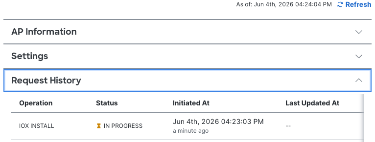
-
You can confirm the install was successfull, when Gateway Status is enabled, and IOX Channel Status is Up for all required APs.
If this is not the case, see the section below on troubleshooting IOX Install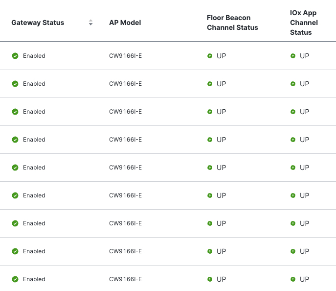
IOX Install Success -
Repeat the above steps for all buildings required.
Troubleshooting
Troubleshooting enabling IOT Services on WLC
In the scenario they do not say SUCCESS, they will instead have an error code. You can click the WLC name to find out more information on what succeeded and what failed.
The following is also relevant if you see a WLC showing as DEGRADED, which in most cases implies IOT Services is not enabled on WLC, but is on Connector.
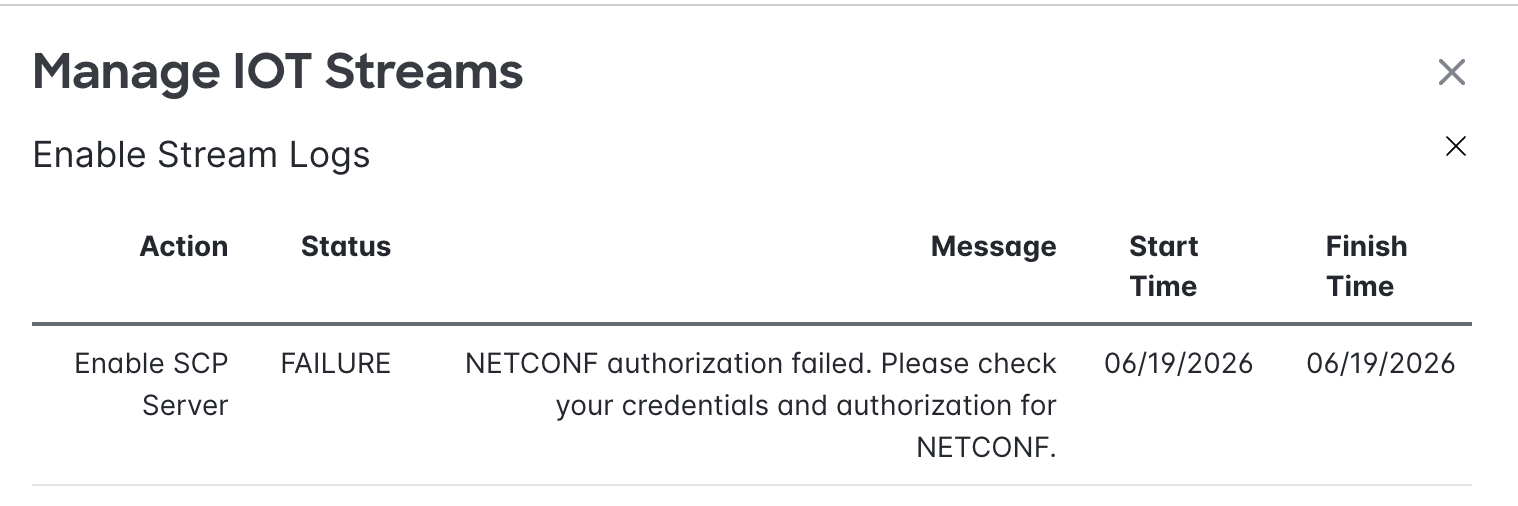
Below is the full list of operations in order when enabling IOT Services on a WLC.
-
Enable SCP Server
-
Get Trustpoint
-
Clean CA Certificate File
-
Clean CA Certificate Key Pair
-
Clean CA Certificate
-
Setup CA Certificate
-
Finish CA Certificate
-
Setup Streaming Token
-
Get Profile
-
AP Profile - Enable App Hosting
-
AP Profile - Enable AP Sensor
-
AP Profile - Enable GRPC Stream
-
Update Stream setup complete
Most common scenarios for errors
-
Netconf credentials are incorrect or user does not have correct privelage levels
-
Required ports are not opened either between WLC and connector, or APs and connector
-
In cases where IOX app fails to install, likely dont have enough storage. Reload AP or log into AP to delete flash.
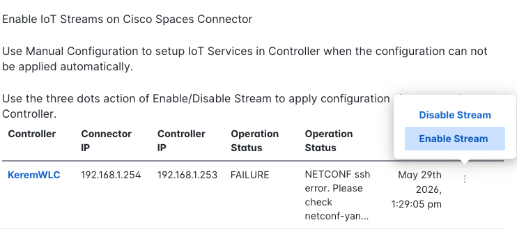
After identifying and resolving any issues, you can use the 3 dots in the Action column to Enable Stream again, re-enabling IOT Services for that selected WLC.
Meraki Deployments
Support for Bluetooth Low Energy (BLE) devices are available on the Cisco Meraki network, in addition to the existing support on the Cisco Catalyst Wireless network.
This enhancement allows the Cisco Spaces platform to seamlessly integrate with BLE devices using Cisco Meraki. With this enhancement, Cisco Meraki BLE devices can now be accessed in various Cisco Spaces applications, including Firehose IoT Telemetry events, IoT Explorer, Signage, and Live Occupancy.
For this feature to work, you must perform specific configurations on the Cisco Meraki network to enable the data transmission to Cisco Spaces. Data flow is limited to read only, meaning Spaces can simply read the configuration and stream data from Meraki. Use cases such are limited to Scan based only, and configuration of BLE devices is not supported.
Meraki use of IOT is only supported using the Spaces Meraki OAuth integration, and not via the API key mechanism
-
Login to the Meraki Dashboard and navigate to Network-Wide > Configure > General. Under Location and scanning verify that the following values are selected
-
Analytics: Analytics enabled
-
Scanning API: Scanning API enabled
-
For Post URL, verify that there are two entries (one for Bluetooth, one for WiFi)
-

If you need to configure any of these Post URLs manually, follow these steps:
Manual Configuration of Scanning API Post URLs
-
Login to Cisco Spaces and navigate to Setup > Wireless Networks > Connect via Meraki Integration > 2) Configure Meraki Integration > Post URL and click Copy next to the URL
-
Return to the Meraki Dashboard and click Add a Post URL. A new line will be created. Paste the value into the Post URL field.
-
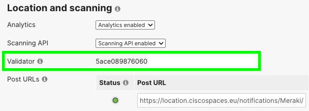
Replace the <URLValidator> part of the URL with the Validator value shown in the field above.
-
Copy the Secret from Spaces > Setup > Wireless Networks > Connect via Meraki Integration > 2) Configure Meraki Integration > Secret Key and paste it into the Secret field next to the Post URL.
-
Select V3 for API version
-
Radio Type WiFi or Bluetooth. You should have one line for each.
-
Click Validate. A new yellow banner will appear to confirm the validation:

-
Click Save to save changes on the page.
-
Navigate to Wireless > Configure > IoT Radio Settings > Bluetooth. Set Scanning to On.
-
Repeat the process for all networks integrated with Spaces.
Meraki Dashboard APIs can be leveraged as a scalable mechanism for enabling IOT Radios. More information can be found here.
-
Navigate to Cisco Spaces > ? (at the top of the page) > Support > Configuration & Deployment Support and click Open a Case. Cisco Support Case Manager will open in a new browser tab.
-
Copy and paste the following message template into your support case:
-
Title: Support for MQTT broker configuration
-
Description:
Hi,
We require support with the configuration of the MQTT broker. Scanning API configurations have been completed.
Please provide the details required for the MQTT broker for the following networks: <list networks>
Thank you.
-
-
Cisco Support Team will provide you the details for the MQTT broker, including the broker password.
-
-
Navigate to Wireless > Configure > IoT Radio Settings > MQTT and enable MQTT telemetry streaming.
-
Configure the MQTT Broker with the details provided by the Support Team.
-
Navigate all the way down on this page and enable Bluetooth telemetry and Wi-Fi telemetry. Ensure all Additional Message fields are checked.
-
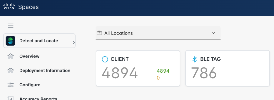
Login to Spaces and navigate to Detect & Locate. Select a location with a Meraki infrastructure and check that the number of BLE tags is non zero.
IoT Services Device Filter
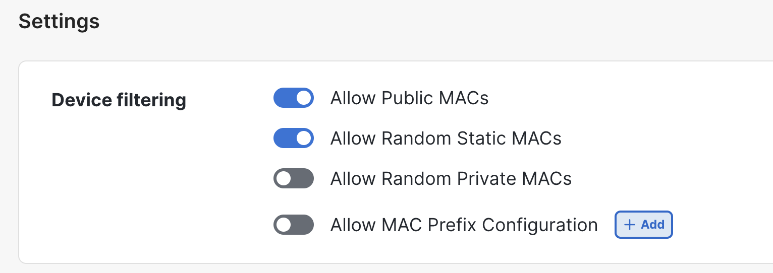
After enabling IoT Services, its generally suggested to enable a device filter. This helps reduce the noise of IoT devices in the dashboard, as well as reduce the load and increase the scalability on the Connector.
To enable IoT Services Device Filter
-
Head to IoT Services > Settings.
-
Ensure the following is configured:
-
Allow Public MACs → True
-
Allow Random Static MACs → True
-
Allow Random Private MACs → False
-
DELIVERING OUTCOMES
Now Cisco Spaces OS is complete, which sets up Spaces in the most successful way for now delivering outcomes. Most outcomes should now simply be enabled in a few clicks, and be compatible to run side by side with each other using the same infrastructure. Each outcome will have its own pre-requisites and steps on how to implement them. Use the following Outcomes Runbooks on steps to deliver.
Smart Workspaces
Cisco Spaces Smart Workspaces transforms traditional work environments into dynamic, data-driven ecosystems that enhance productivity and collaboration. By leveraging advanced location-based services, Smart Workspaces enables organizations to optimize space utilization, streamline operations, and create a more engaging workplace experience.
Asset Tracking
Lack of real-time Asset tracking solutions can add critical bottleneck to your supply chain operations and in the healthcare industry, cause life-threatening delays.
With Spaces native apps you can track all devices connected to your network in real time and with a host of partner apps & BLE devices, you can monitor and manage all critical or high value assets in your campuses.
Occupancy
Cisco Spaces provides a comprehensive platform for leveraging location-based services to enhance operational efficiency and decision-making.
The "Occupancy" outcome within Cisco Spaces is designed to monitor and analyze the utilization of physical spaces, allowing organizations to optimize their environments effectively. By integrating real-time data from connected devices and sensors, users can gain valuable insights into space usage patterns, identify trends, and ensure compliance with occupancy regulations.
This documentation will be a guide through the setup process, enabling an organization to harness the full potential of Cisco Spaces for occupancy management and drive informed decisions for space planning and resource allocation.
Captive Portal
A captive portal is the first touchpoint with your business for customers on Wi-Fi. It provides an opportunity to engage with customers who connect to Wi-Fi, offer relevant information, drive monetization, and potentially acquire customer information. Captive portals enable businesses to choose from multiple authentication mechanisms and deliver targeted experiences based on business rules. They can recognize repeat visitors and deliver customized offers, enhancing customer engagement and loyalty.
OpenRoaming
OpenRoaming enables secure, seamless, and automatic network connectivity by eliminating tedious Wi-Fi guest onboarding processes and the risk of connecting to rogue SSIDs. This is especially helpful for a mobile device user trying to access the internet because OpenRoaming removes the need to choose between multiple SSIDs, or enter insecure, shared credentials on poorly designed captive portals.
Indoor Navigation
Indoor Navigation enabled indoor and campus based wayfinding leveraging Cisco Access Points to deliver accurate positioning and routing. Indoor Navigation helps guests and staff effectively find locations within a building, saving time and effort needed.
Smart Rooms
Cisco Smart Rooms seamlessly integrate your existing Cisco Webex devices with your Building Management System (BMS) to provide demand control ventilation, optimize the experience, wellbeing, and productivity of your existing spaces when in use, and reduce energy use when spaces are not in use.
Space Explorer Web App
The Space Explorer Web App allows flexible access with SSO login (via Webex, Microsoft, and Google Login - more details below) to authenticate end users. The Web App is complementary to the Space Explorer Kiosk app meant to be displayed on a lobby display. In addition to room occupancy and calendar status, the Space Explorer Web App adds Smart Desking functionality to Cisco Spaces workplace experience applications. It is a flexible workspace solution that allows employees to reserve dynamically allocated desks (“Hot Desks”) instead of having assigned seating. It is a key part of hybrid work models and is commonly managed through IoT, AI, and cloud-based platforms.
CAVEATS & TIPS
Placing GPS Markers
As mentioned above, the preferred route for GPS configuration is to use the Network Maps Calibration tool
GPS Markers are utilised in Cisco Spaces, any time converting between x,y and lat,lon locations.
For detailed best practice, refer to this Knowledge Article.
This function is used by the following apps today, but is likely to expand. Its recommended to implement GPS markers in all deployments of Spaces, even if these features are not used today.
-
Space Manager
-
Wayfinding
-
Smart Workspaces
-
App Center delivered use cases
Recommendation is to place 3 markers per floor. Use OpenStreetMap to gather the appropriate lat,lon details. Use prominent features (such as corners of the building) to accurately place markers.
Failing to follow the above will result in a poor experience.
-
Log into Catalyst Center, and navigate to Design > Network Hierarchy, on the left pane select a floor.
-
From the map toolbar, click the GPS Markers toggle.
-
From the map left pane, click the GPS Markers icon.
-
Use the drawing tool to place the GPS marker:
-
Click on the map to place the GPS marker.
-
In the Place Markers pop-up window, enter the name, latitude, longitude, x and y coordinates in the appropriate fields.
-
Click Add GPS Marker.
-
-
Repeat these steps until there are three GPS markers on the floor map in a polygon-shape.
-
Click Save from the map toolbar.
The GPS marker is an attribute of the building and can be applied to all the floors of the building.
Wireless Network Design Tips
Overview
The density of a wireless deployment will be a major factor in the accuracy of occupancy depending on the specific outcome needed. Occupancy using Wi-Fi may not require a dense coverage for campus and building occupancy details as it relies on devices connecting to the Wi-Fi network. Moving into an outcome where Floor and Zone level accuracy is required, a denser network deployment is highly recommended.
AP Density Assessment
APs needs to be accurately placed on network maps to ensure the best outcomes.
-
WLC managed Aps :
-
AP Auto Locate (preferred)
-
Note: WLC version 17.12.2+ (required)
-
-
AP placement on Catalyst Center (site survey to confirm AP location – required)
-
AP Auto Locate
-
AP Auto locate can provide most accurate information about AP placement
-
Here are more details : AP Auto Locate
For best practice guidance for implementing AP Auto Locate please review this guide here.
Catalyst Center
4 or more (minimum of 3) GPS Markers are required, and each should be placed at least 20 meters apart from each other. This is to ensure proper scaling and orientation of Catalyst Center network maps when aligning with Digital Maps on Cisco Spaces.
More details here : GPS Markers for network map and wayfinding map geo-alignment
Meraki Cloud Managed
Please refer to the following :
-
Manual placement of Meraki APs on Meraki Dashboard network map
-
Additionally, the following video will help illustrate the alignment process: https://app.vidcast.io/share/f1faa92d-66e3-4da1-be78-0b6ec79e9123
AP Placement
The density of AP deployment in terms of “1 AP per X sq ft” can be found by using:
(Number of APs on floor) / (Total Sq ft of the floor)
Number of APs on floor
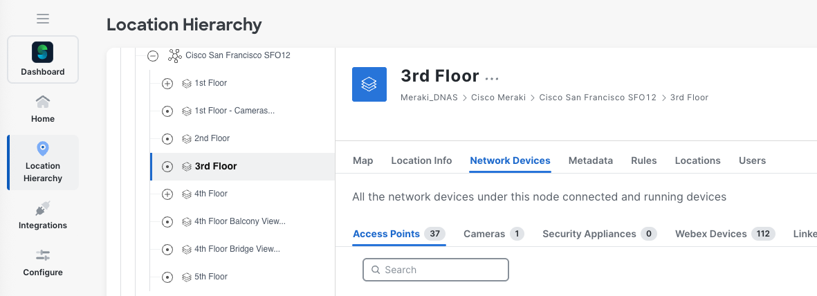
This information is available from the Spaces Dashboard
Navigate to Location Hierarchy, then to the desired building and select the desired floor. On the main page select the Network Devices tab. You will see the number of APs next the Access Points section.
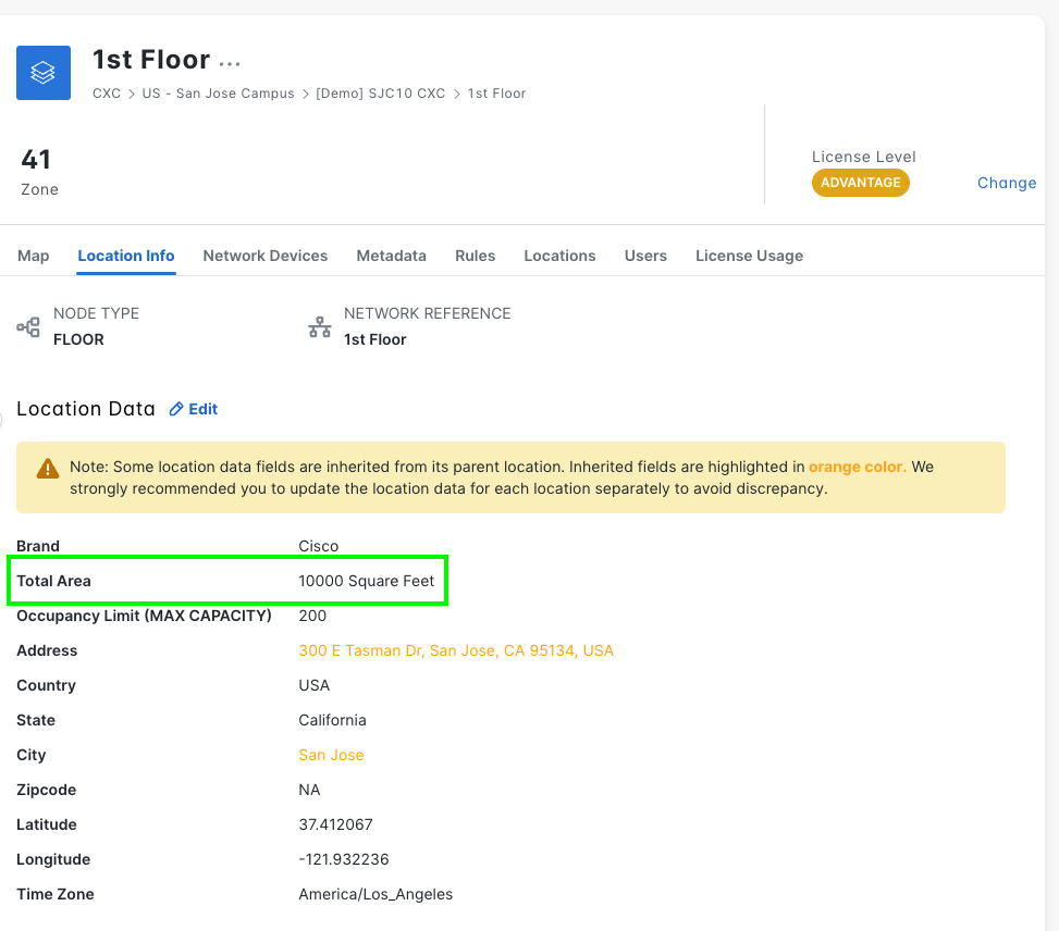
Total Sq ft of the floor
-
This information can be retrieved from the dashboard Location Hierarchy section as long as the manual input has been updated accurately
-
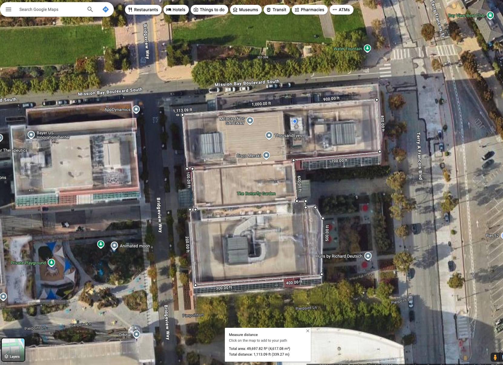
Otherwise, estimate the floor using Google Maps by providing exact building address and using measure distance feature as shown below
-
This assumes that the floor plan matches the footprint of the building
-
The example below draws along the rooftop of the building as it matches the floor plans within the building
-
Once the points are all connected around the perimeter, Google maps will provide a square footage calculation in the window and the bottom center of the screen
-
Kiosk List of API Endpoints for Firewall Settings
|
IO Region |
EU Region |
SG Region |
|---|---|---|
|
wss://webex-api-server.dnaspaces.io |
wss://webex-api-server.dnaspaces.eu |
wss://webex-api-server.ciscospaces.sg |
Meraki Firewall Issues
Depending on security policies of the Meraki environment the following IP addresses may need to be added to be permitted for communication with Cisco Spaces:
These settings are found under Organization > Settings > Login IP ranges > Allow dashboard API Access to these IP Ranges.
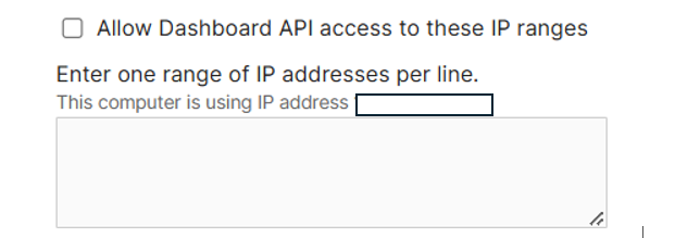
Caution: Selecting “Allow Dashboard and Dashboard API Access to these IP Ranges” could restrict access to the Meraki Dashboard. Ensure that “Dashboard API access” is selected.
Exercise due diligence before enabling any new security restriction. Important API applications could unwittingly be locked out (e.g. those provided by ecosystem partners or service providers) from the organization if their IP ranges are not included before enabling this feature.
|
US |
EU |
SG |
|---|---|---|
|
34.192.26.106 |
52.208.15.59 |
3.1.251.174 |
|
52.206.67.43 |
54.220.148.167 |
13.215.110.252 |
|
3.208.52.128 |
54.220.45.63 |
|
FAQ
Acronyms used
API - Application Programming Interface
BLE - Bluetooth Low Energy
CAD - Computer-Aided Design
DNS - Domain Name System
GPS - Global Positioning System
IoT - Internet of Things
NETCONF - Network Configuration Protocol
NMSP - Network Mobility Services Protocol
SNMP - Simple Network Management Protocol
SSID - Service Set Identifier
vCPU - Virtual Central Processing Unit
VM - Virtual Machine
WLC - Wireless LAN Controller
XREF - Cross Reference
What is Cisco Spaces OS and what are its key features?
Cisco Spaces OS is the fundamental software platform for managing and deploying location-based services within the organisation. It acts as the base installation and seamlessly integrates a suite of critical components designed to streamline operations and enhance data utilisation.
Key features include:
-
Onboarding data from various sources like Catalyst Center, Wireless LAN Controllers (WLC), and Meraki for a holistic view.
-
Unified location hierarchy configuration for organised network views and access point deployment management.
-
Digital Map creation using uploaded CAD files for visual representation of spaces, enhancing navigation, and planning.
-
Enabling IoT streaming services, allowing organisations to leverage real-time data insights for better decision-making.
How do I onboard Cisco devices and intake telemetry data into Spaces OS?
Spaces OS supports onboarding data from various Cisco platforms, including Catalyst Wireless, Catalyst Center, and Meraki. Each platform has a specific process for integration.
For Catalyst Wireless:
The Cisco Spaces Connector needs to be installed on a virtual machine, allowing communication with the WLCs. Detailed instructions on configuring the connector, adding WLCs, and establishing connectivity can be found in the Cisco Spaces OS Runbook.
For Catalyst Center:
Ensure Catalyst Center is at Release 2.1.2.3 or higher and accurately placed GPS markers. The integration process involves creating a token in Cisco Spaces, activating CMX Servers/Cisco Spaces in Catalyst Center, and configuring service selection under the Wireless tab in Network Settings.
For Meraki Wireless:
A Meraki account can be connected to Cisco Spaces via the Meraki dashboard. Options are to choose to integrate into an existing Spaces account or create a new one. Detailed steps for both options are available in the Cisco Spaces OS Runbook.
What is Location Hierarchy in Cisco Spaces OS, and how do I configure it?
Location Hierarchy enables the ability to organize the network view within Cisco Spaces based on the physical business locations and access point deployments. This hierarchy can be structured based on brands, regions, campuses, and other relevant taxonomies.
To configure:
-
Access the Location Hierarchy feature under Setup > Locations & Maps.
-
Review existing hierarchies ingested from integrated platforms like Catalyst Center, Meraki, and Webex Control Hub.
-
Merge similar location hierarchies using the 'merge with' option.
-
Configure metadata like Time Zone, Capacity, and Area for accurate occupancy computation.
Why are GPS Markers important in Cisco Spaces OS, and how do I place them?
GPS Markers play a crucial role in converting between x,y and lat,lon locations within Cisco Spaces, ensuring accurate location-based services. They are vital for apps like Space Manager, Wayfinding, and Smart Workspaces.
To place GPS Markers:
-
In Catalyst Center, navigate to Design > Network Hierarchy and select a floor.
-
Enable the GPS Markers toggle from the map toolbar.
-
Use the drawing tool to place markers on the map, providing a name, latitude, longitude, and x, y coordinates for each.
-
Place at least three markers per floor, using prominent features like building corners for accuracy.
How do I create Digital Maps in Cisco Spaces OS?
Digital Maps in Cisco Spaces provide visual representations of the spaces, enhancing navigation and planning.
To create a Digital Map:
-
Go to Setup > Locations & Maps and click the Digital Maps tab.
-
Select the desired building and click "Add Digital Map."
-
Confirm the building's street address for accurate location pin placement.
-
Add floors by clicking "Add new floor" and providing necessary metadata like level numbers and short names.
-
Upload CAD files or Vector PDFs for each floor, ensuring one file per floor.
-
Review and confirm the uploaded files, then submit for processing.
-
Once processed, review the unpublished Digital Map and add/edit room labels.
-
Publish the building to make the Digital Map available in Cisco Spaces.
What are some best practices for uploading CAD files for Digital Maps?
Please refer to the US National CAD Standard for guidance on layer details.
There are 3 main elements for a great CAD file (.dwg) or Vector PDF with layers:
-
Architectural layers (e.g. walls, doors, stairs, windows, etc.)
-
Furniture layer
-
Space names / IDs / labels
Additional best practices:
-
Spaces (Space Type) marked clearly or detail provided. For example, a space with a collaboration endpoint will need a room or desk to assign it to.
-
Have clearly defined or marked POIs like stairs, bathrooms, elevators etc.
-
Room Names:
-
Should be intuitive for end-users
-
Should be made as short as possible whilst keeping readibility (i.e. don’t include building/floor/zone names, room size, room type, etc.)
-
Ideally the room names in the CAD file match the workspace name in Webex Control Hub. Without this, manual mapping of room name to Webex Control Hub workspace must be done.
-
Sometimes, a CAD or Vector PDF file can have multiple such identifiers for the same room. In this case, please leave a comment in the upload workflow with which identifier should be used as a name for the spaces.
-
-
Provide clear layer names in CAD. For example: "A-Furn" (furniture), "Doors" (for doors), ”Windows” (for windows), etc.
-
Keep elements in separate layers. Example: walls, doors, labels in their own layers.
-
Cross Reference (XREF) layers will not be processed. “Bind” them into a single .dwg when exporting from AutoCAD or another program.
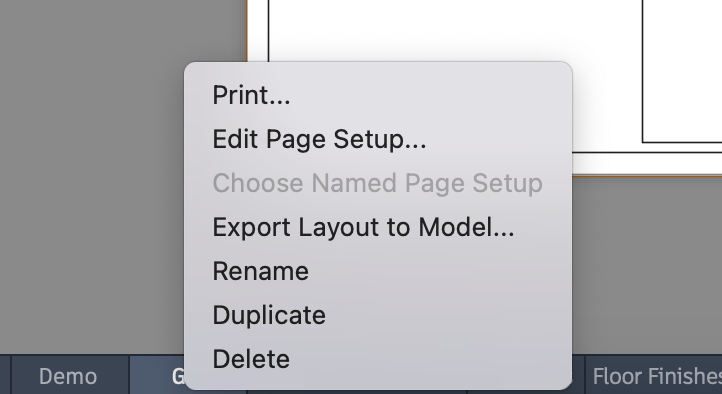
How do I export a complex CAD (.dwg) file from AutoCAD with multiple layers that I do not want to include for the Digital Map?
If the CAD (.dwg) file has as a “Layout” tab with the exact layers and objects needed:
-
Right-click on the tab (bottom of the application window on macOS)
-
Choose the “Export Layout to Model…” option
The resulting CAD (.dwg) file will only contain the layers and objects visible in that Layout.
What kind of changes can I expect when re-uploading CAD files to modify existing Digital Maps?
There are a few scenarios where intentionally or unintentionally re-upload CAD files may be necessary:
-
After uploading CAD files for the first time (before finished processing), canceling is perfectly acceptable. Canceling the processing will make it possible to choose different files (if chosen mistakenly or realizing some changes were needed in the file contents) or add/remove files from processing. Otherwise, waiting for the first round of processing (per building) is necessary before adding or removing any floors.
-
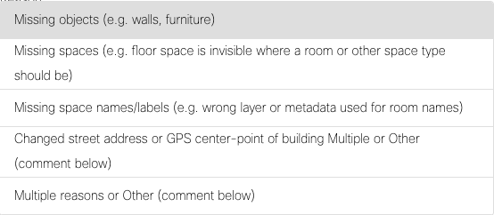
After map processing has completed and there are missing objects in the Digital Map (among other reasons - see below), re-upload the exact same file as before and a new reason, comments, and attachments modal appears inline. The reason dropdown categories are:
-
Missing objects (e.g. walls, furniture)
-
Missing spaces (e.g. floor space is invisible where a room or other space type should be)
-
Missing space names/labels (e.g. wrong layer or metadata used for room names)
-
Changed street address or GPS center-point of building
-
Multiple reasons or Other (comment below)
-
Provide additional comments to help our mapping team review the AI processed maps and provide a faster/better update. Optionally include an image with annotations for a holistic picture of the corrections needed.
-
Similar to scenario 2 above, the Location Hierarchy has changed and the exact same files are used to create the same Digital Map in a new Location. Use the appropriate reason dropdown option: “Changed street address or GPS center-point of building”. This also applies to re-uploading when the Cisco Spaces mapping team has declined/rejected a CAD file because the building could not be found on the world map. Please provide additional details in the comments field to help the mapping team accurately align the Digital Map on the world map for accuracy in outcomes.
Note: a building can only exist in one place in the world and cannot be duplicated across multiple Locations in the Location Hierarchy or in multiple Cisco Spaces Tenants. Only the most recent upload will work correctly for outcomes such as Pathfinder on Space Explorer Kiosk and Indoor Navigation App Clip for turn-by-turn blue-dot wayfinding indoors.
-
After CAD files are finished processing and Published, it is safe to upload additional floor files or modify existing with new file versions. Follow the same workflow as before, but either create new floors (w/ metadata) or check the boxes for floors to update specifically to change the files.
Note: re-uploading unchanged floors is not necessary. When re-uploading, only check the boxes for the floors that need to be updated.
-
Currently, it is not possible to delete individual floor Digital Maps. Please open a TAC case to request help removing unwanted files until this feature is available in the dashboard.
-
Currently, it is not possible to process individual floors in parallel in the same Building. Either cancel a map processing job and re-upload or wait for the current process to complete and Publish. Then, proceed with the next upload. Multiple parallel floor uploads in the same Building will be possible in a future update.
Will Webex Workspaces remain connected to the Meeting Rooms after re-uploading CAD files to modify Digital Maps?
There is not currently a way to edit a Digital Map directly with new walls, rooms, or furniture after a CAD file has been processed. To make physical layout changes, upload a modified CAD file to the Cisco Spaces Digital Map platform, and it will attempt to carry forward metadata (e.g. Webex Workspace connection, Meeting Room name manual edits). Generally, metadata associations stay intact in the database as long as the internal identifiers have not changed. Typically, a furniture layout will not create new identifiers, but physically moving walls or changing a room name in the CAD file will create new entities on the backend and erase previous manual edits in the Digital Map Editor (e.g. room name). IoT Sensor associations should carry forward as well.
The Digital Map Editor (under Setup > Locations & Maps > Digital Maps) provides an interface to make lightweight, metadata changes to previously processed CAD files. For example: space names, space IDs, and space types. While it is quite easy to manually make these edits, the source CAD files do not receive those edits.
It is important to always keep your source CAD files up to date so that when they are re-uploaded for processing at any point in the future to update the physical layout, space metadata (e.g. name, ID, type) remains intact and is not reverted. If this metadata remains identical to the previous version uploaded and processed, manual edits will carry forward. Any diff in a new file version will overwrite manual edits that conflict.
If new or moved rooms' names are close matches to their respective Webex Workspaces, auto-connecting in Space Manager > Manage Rooms should reduce manual work to associate all collaboration devices with rooms post-processing CAD files.
Note: Webex Workspaces must be assigned to a Location and a Floor in Control Hub to benefit from auto-connect based on name matching. IoT Sensors will need to be re-added if physical spaces or name have changed significantly, as they do not benefit from auto-connection by name.
What do I need to keep in mind for Campus Wayfinding (i.e. indoor-outdoor and inter-building navigation)?
There are several factors that affect Campus Wayfinding and decrease time to process CAD files:
-
Campus wayfinding is performed within a single campus element in the hierarchy. Therefore navigation between buildings must be within the same campus. The campus element is defined as the immediate parent of any building.
-
A group of Buildings (i.e. Campus) MUST fit within a 100km² area (roughly 10km x 10km). To be safe, the distance between the 2 furthest buildings must be no more than 8km.
-
Geo-alignment on the world map is essential. Elements included in the CAD files (e.g. bridgeways, paths, etc.) can help align Buildings to ensure smooth transitions between Buildings in a Campus.
How do I enable IoT Services in Cisco Spaces OS?
IoT Services extend the capabilities of Cisco Spaces by enabling BLE on compatible access points and creating a telemetry stream for data.
To enable:
-
Navigate to IoT Services on the left-hand side menu.
-
Ensure all prerequisites are met and click the "Activate" button.
-
Select "Wireless" and proceed to the next step.
-
The Activation Screen shows the number of active connectors and controllers.
-
It can be chosen to activate IoT services everywhere or customize the deployment by selecting specific connectors, controllers, or APs.
What firewall settings are required for Cisco Spaces Kiosk to function correctly?
To ensure Cisco Spaces Kiosk functions properly, firewall settings might need to be adjusted to allow communication with specific API endpoints. The required endpoints vary based on the Spaces region (IO, EU, or SG).
Refer to the "Kiosk List of API Endpoints for Firewall Settings" section in the Cisco Spaces OS Runbook for the complete list of endpoints for each region. Make sure the firewall permits traffic to these endpoints to prevent connectivity issues with the Kiosk application.
If I complete AP Auto Locate in Spaces will the AP placement sync into Catalyst Center?
No this is not functionality that is available today. AP Auto Locate is planned to migrate to both Catalyst Center and Meraki, so placement is done in those platforms and passed into Spaces.
How can I confirm if netconf is enabled on my WLC?
You can SSH from connector to WLC over the netconf port number (default 830).
ssh -p 830 -s <username_configured_in_Spaces>@<controller_IP> netconf
If the user connects, this proves that connector can establish netconf to WLC using the give user.
APPENDIX
Spaces OS Diagram
Spaces OS Checklist
- Prerequisites
- Verify all necessary firewall rules are in place for Spaces connectivity
- Retrieve metadata for locations (need max occupancy for floors and building, total area sq ft/mt, and time zone)
- CAD drawings acquired
- Smart Account linked
- Catalyst managed specific environments
- Configuration and Activation of Spaces Connector(s)
- Wireless controller(s) added
- Catalyst Center or Meraki integration
- Webex Control Hub Integration
- Network Hierarchy Merges
- Metadata entered into hierarchy
- Digital Map(s) published
- Network map(s) and Digital map(s) aligned
- Devices (e.g. Webex) mapped to rooms
- AP placements on map(s) [one of the following]
- AP AutoLocate (auto or manually placed)
- Placed in Catalyst Center or Meraki Dashboard
- IoT Services Activated
- Live Occupancy SSID Filters set