Intro
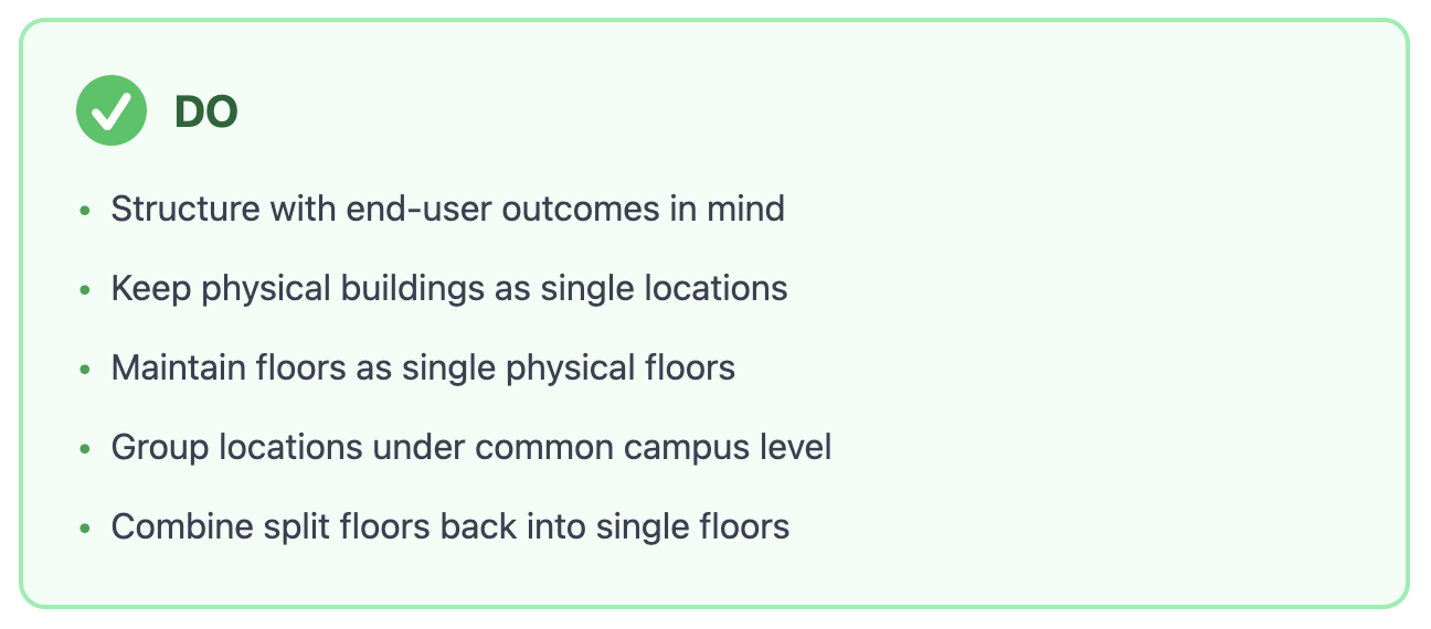
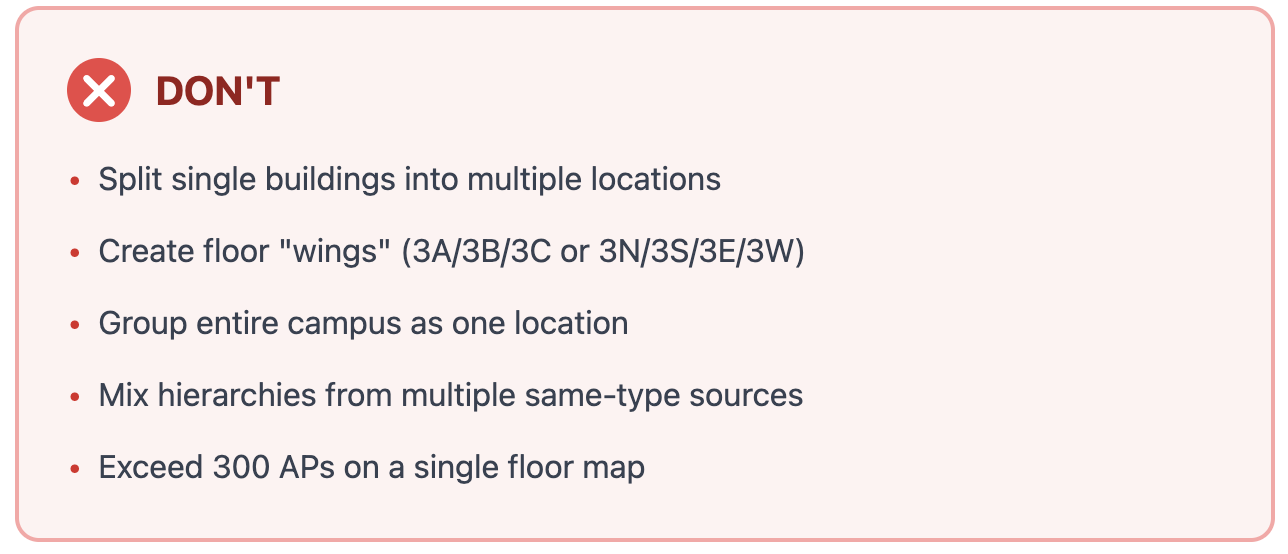
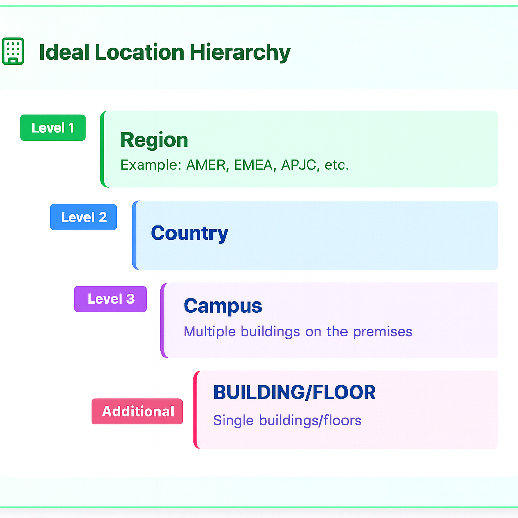
A well-structured Location Hierarchy is the blueprint for all Cisco Spaces outcomes. It is important to structure the hierarchy with end user outcomes in mind as employees, guests, etc. may need to consume services in more intuitive ways than how systems are setup for IT or facilities outcomes. For example, a guest to an office space may not understand the layout of the building, so the Indoor Navigation feature on their phone may improve their ability to find different parts of the building. If the maps and directions are not intuitive, users may become confused and get lost more easily. Single physical buildings are then recommended over splitting into multiple buildings. Keeping floors as single floors per physical space instead of separating into “wings” or towers is strongly encouraged.
There can always be technical and physical limitations that may need clever solutions or feature enhancements, so it is not expected to force a particular Location Hierarchy. However, a best effort should be made to follow best practice and guidance in this Cisco Spaces Knowledge Article.
Some merges are more complicated than others. If you have any doubts or would like to consult with an expert, please reach out to your Cisco account team or the Cisco Spaces product team for guidance.
Example Logical Hierarchy
Location A (a physical building and/or street address - not a campus or group of phsyically separate buildings)
↳ Ground Floor (a single logical/physical floor in the building - not "wings", quadrants, or sections)
↳ Floor 1
↳ Floor 2
↳ etc.
Location B  (a separate physical building and/or street address - not a campus or group of phsyically separate buildings)
↳ Floor 22  (a single logical/physical floor in the building - not "wings", quadrants, or sections)
↳ Floor 23
↳ Floor 31
↳ etc.
https://app.vidcast.io/share/8fb202a5-e26d-480f-962c-ea77748bf033?t=139
Source Scenarios
Single Source
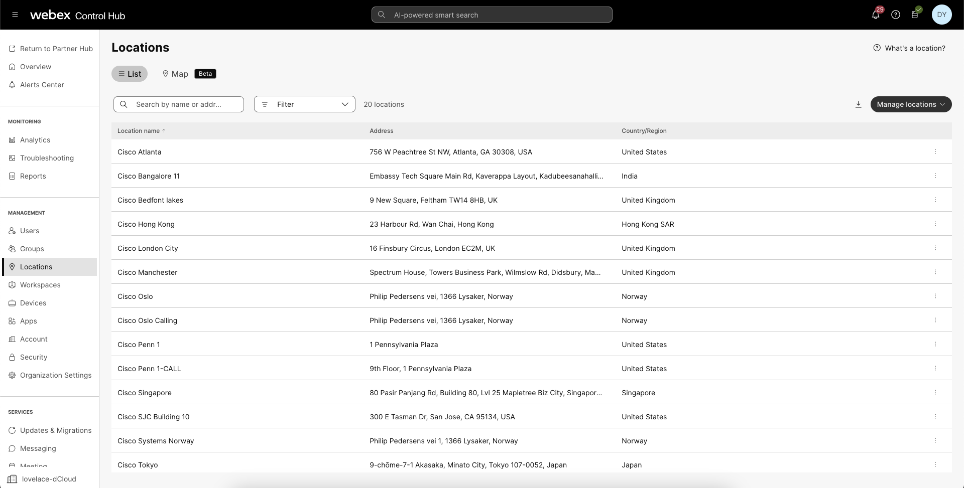
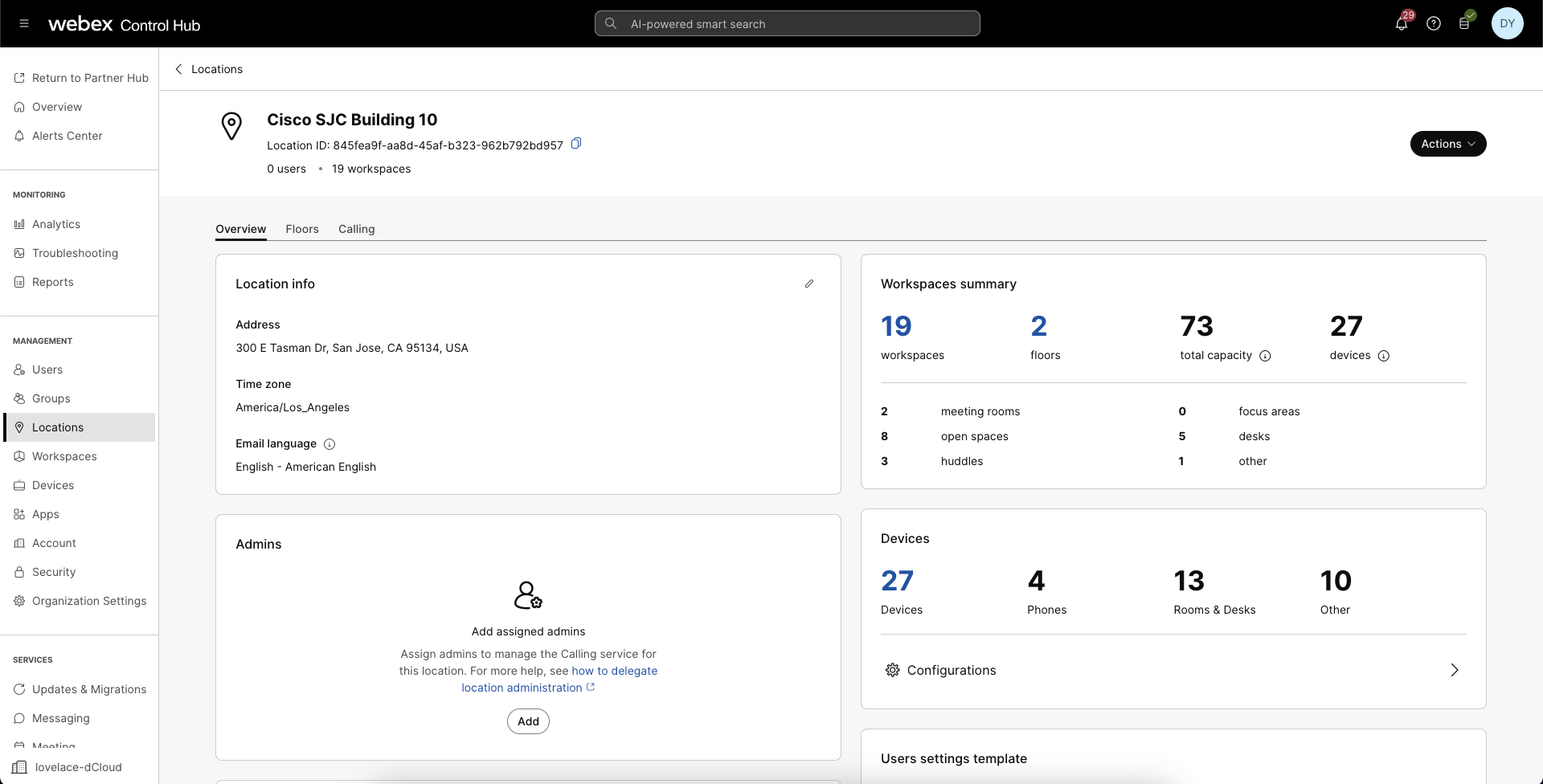
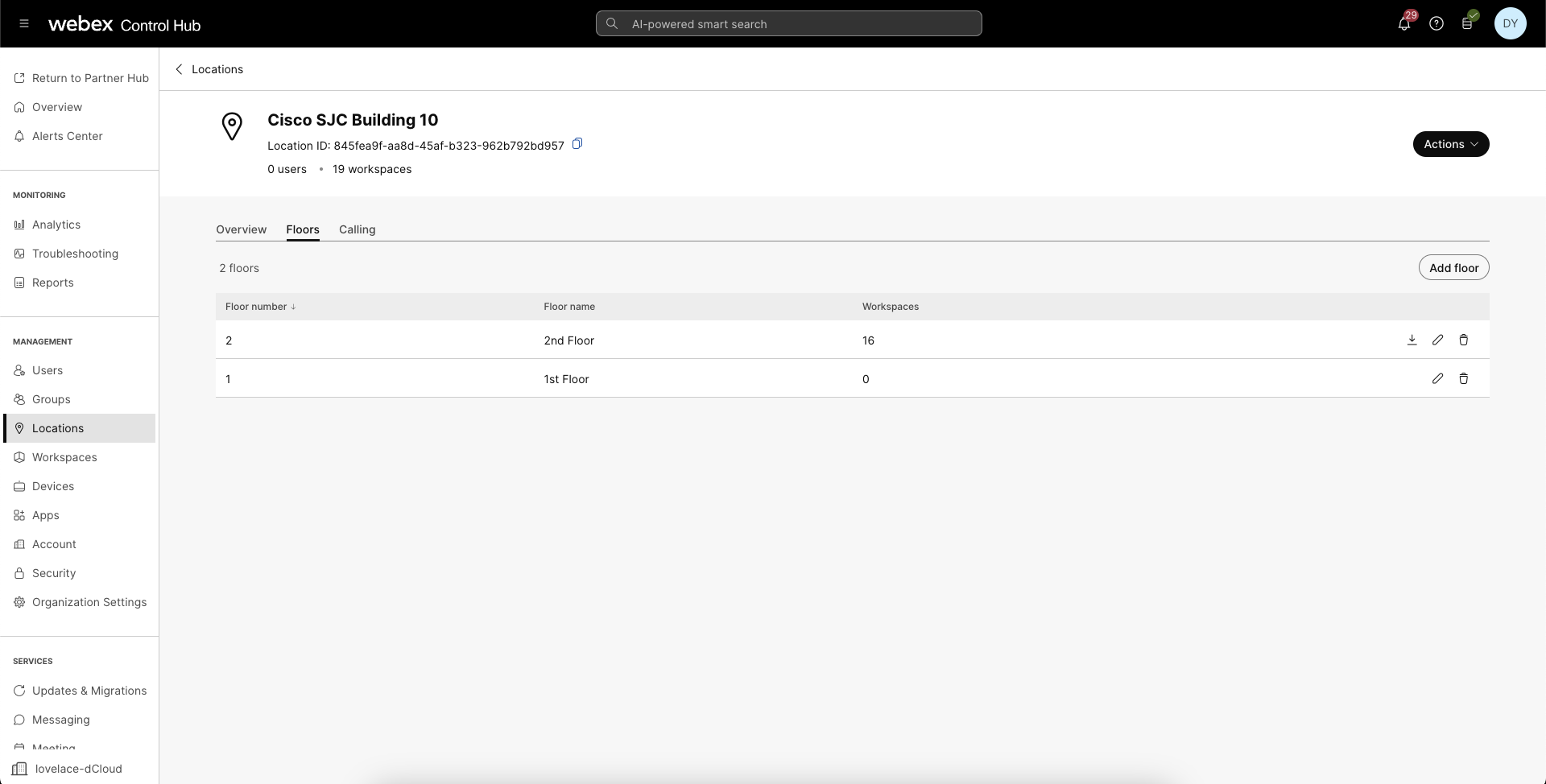
Webex Control Hub Org
The Webex Control Hub Org location hierarchy is the simplest among the sources. It is “flat” in the sense that Location nodes are not grouped into regions, campuses, or any other nesting structure. If the Webex Control Hub Locations have been re-purposed to add multiple physical buildings under a single Location in order to treat it as a “campus”, these physical buildings should be separated into unique Locations (one per address/building). Sometimes multiple physical buildings share the same street address. These should also be separated and can have the same street address. There will be an option to setup unique latitude/longitude values in Cisco Spaces as part of the AI Digital Map conversion process.
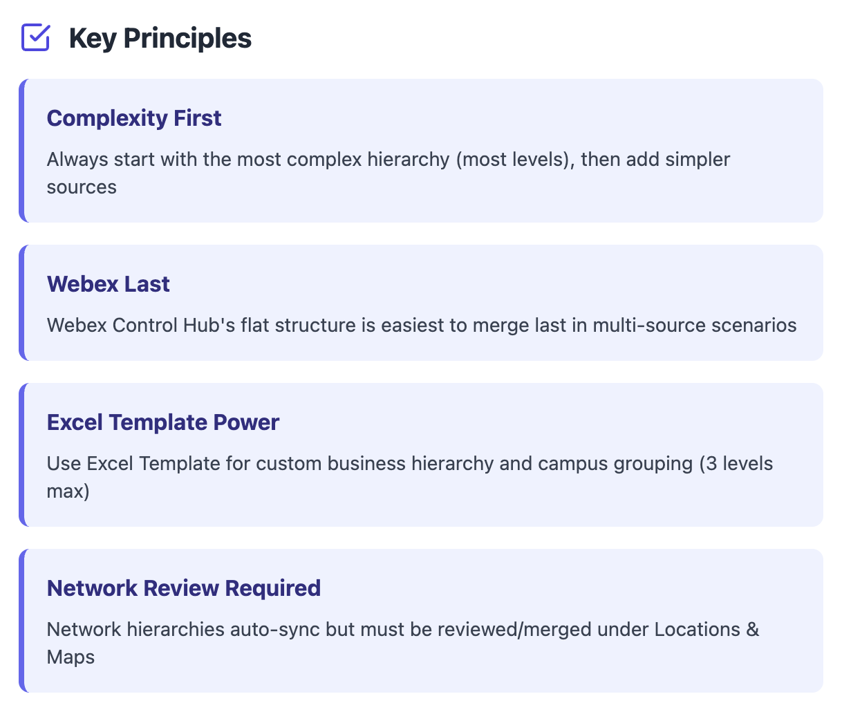
Cisco Spaces has an option to re-group the “flat” Location from Webex Control Hub into a desired business hierarchy. In this case, creating the Cisco Spaces Location Hierarchy using the Excel Template method is encouraged first, then merging each Webex Control Hub Location + Floor(s) into the hierarchy created from the Excel Template. Refer to the Cisco Spaces - BlackBelt Training - Locations & Maps video to learn more.
Note: the Excel Template hierarchy method provides up to three “levels” in the Location Hierarchy (for example: region, country, campus), then the building Location itself. Floors are then created by merging another source into the Excel Template hierarchy and “creating” (instead of “merging”) the individual floors. If you skip merging another source until later, the Digital Maps CAD file upload workflow has steps to manually create floors as well.
Note: proceed with caution when creating the Location Hierarchy using a “flat” hierarchy from Webex Control Hub. Certain outcomes may be limited. For example, Campus Wayfinding may not work properly unless Locations are grouped into Campuses. See: FAQs below.
Catalyst Center
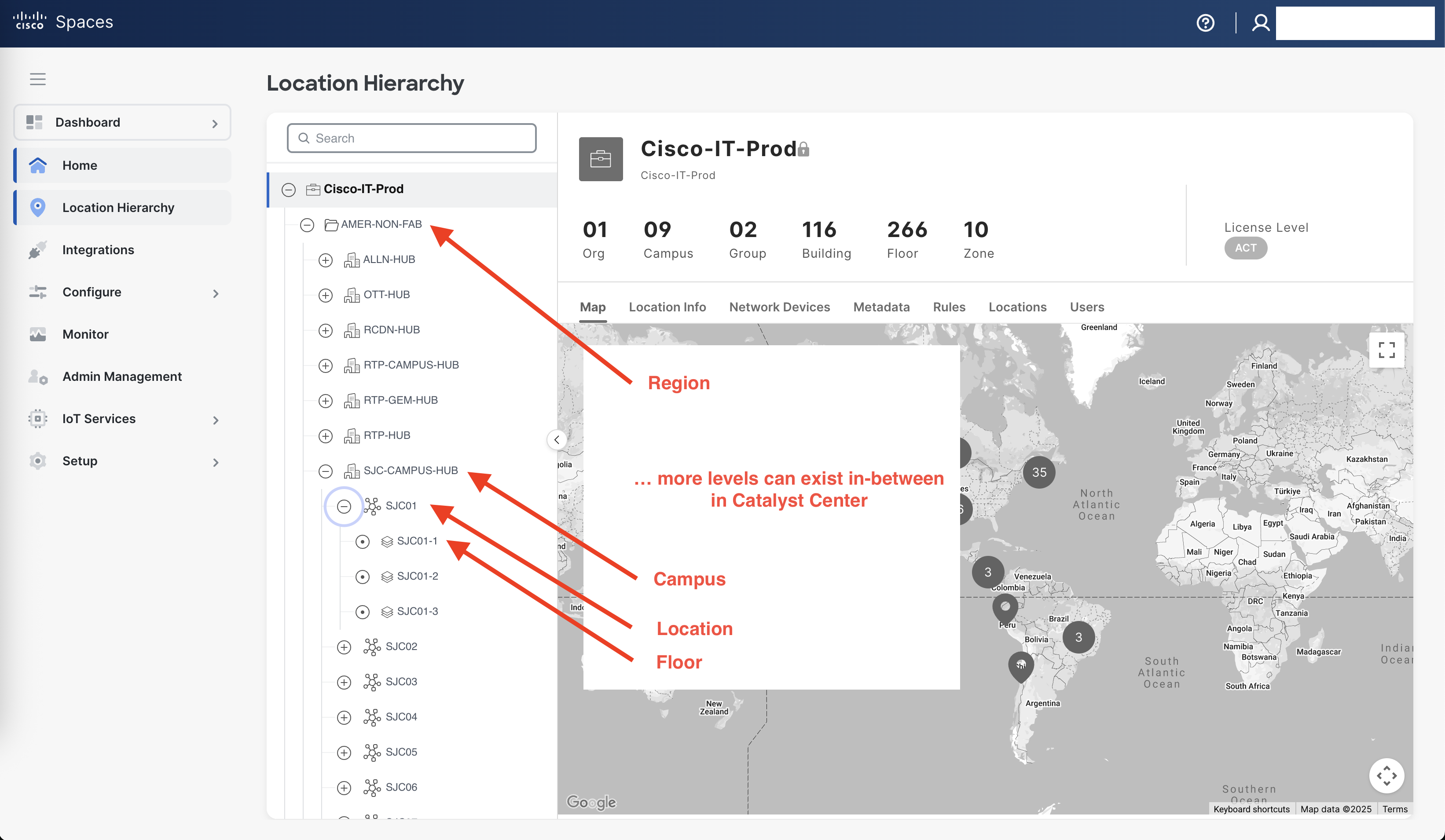
A Catalyst Center hierarchy provides the most “levels” in the Cisco Spaces hierarchy, which often makes this one of the first sources to merge in multi-source scenarios. The Catalyst Center hierarchy can often be synced and created without modification.
Note: network hierarchies, such as Catalyst Center, will appear in the Cisco Spaces Location Hierarchy automatically. However, for many workflows and outcomes, especially uploading CAD files to convert to AI Digital Maps, you must create/merge the Catalyst Center hierarchy under Setup > Locations & Maps > Locations > Review (button in the top right) in order to proceed.
Note: proceed with caution when creating the Location Hierarchy using a complicated Catalyst Center hierarchy. Certain outcomes may be limited. For example, Campus Wayfinding may not work properly unless Locations are grouped into Campuses. In some cases, each Catalyst Center Locations may be in its own Campus as opposed to grouped under a common Campus level. See: FAQs below.
Meraki Org
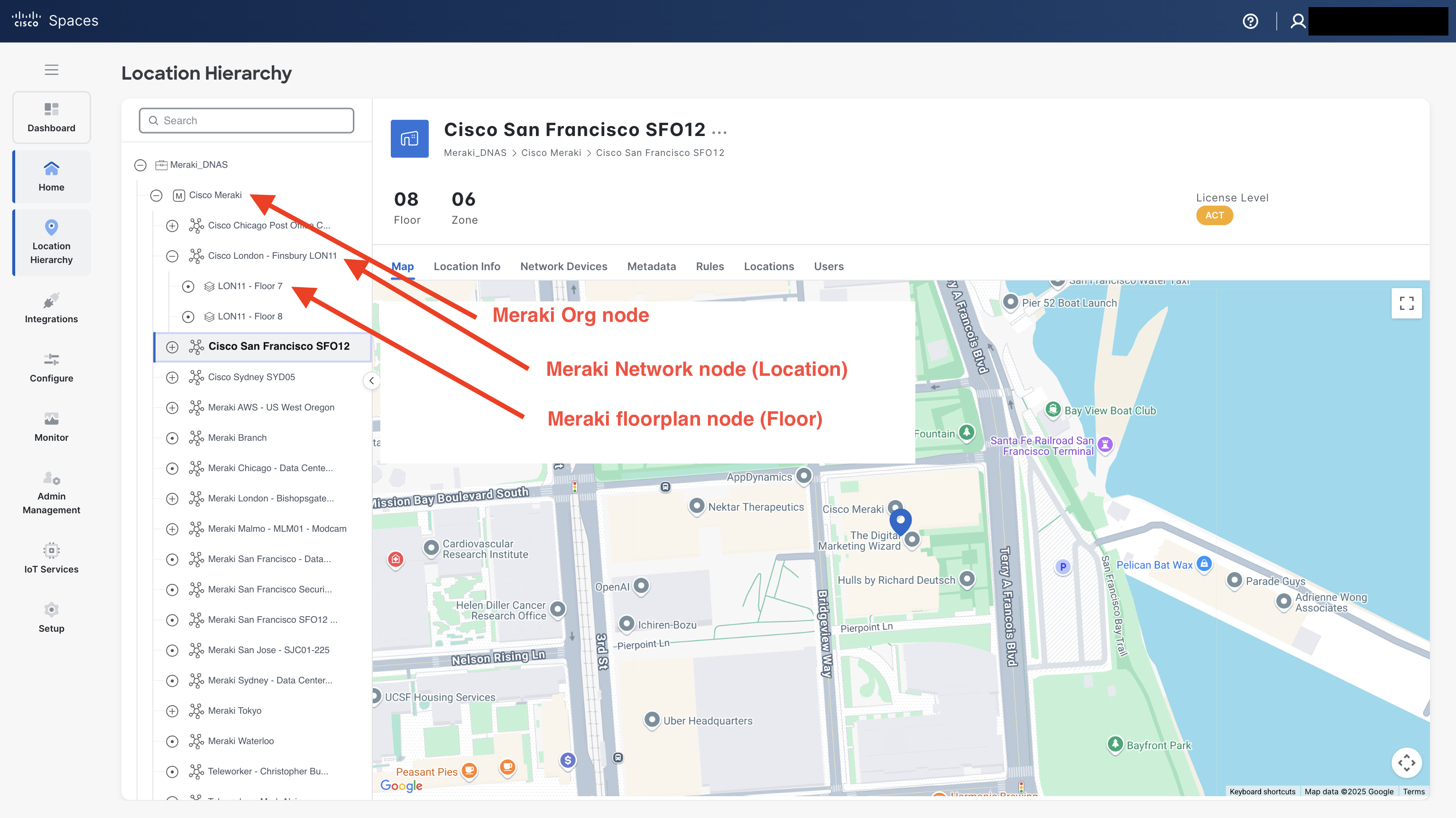
A Meraki Org hierarchy is similar to a Webex Control Hub Org hierarchy in that it has limited levels by default. It does include one additional “node” in the hierarchy, which is the entire Org itself (Org Name) with Networks (Locations) in a “flat” hierarchy under it, followed by floorplan(s) (floors) under each Location.
Note: network hierarchies, such as a Meraki Org, will appear in the Cisco Spaces Location Hierarchy automatically. However, for many workflows and outcomes, especially uploading CAD files to convert to AI Digital Maps, you must create/merge the Meraki Org networks and floorplans (floors) under Setup > Locations & Maps > Locations > Review (button in the top right) in order to proceed.
Note: proceed with caution when creating the Location Hierarchy using the default Meraki Org hierarchy. Certain outcomes may be limited. For example, Campus Wayfinding may not work properly unless Locations are grouped into Campuses. By default, all Meraki Networks (i.e. Locations) are in a “flat” hierarchy under the Org node of the hierarchy. It is recommended to use the Excel Template hierarchy method first, then merge the Meraki Org hierarchy into it. Please account for the Meraki Org node and where it can/should be merged into the Cisco Spaces Location Hierarchy as well. See: FAQs below.
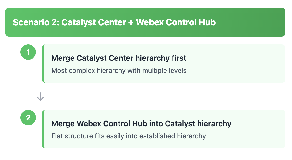
Two Sources
First Source
Recommended: Excel Template or Network (Catalyst Center or Meraki Org)
Each of the network hierarchies typically have more complicated hierarchies, so they are recommended for creating the base structure of the Cisco Spaces Location Hierarchy.
If there are two network sources, it is recommended to start with the Meraki Org, then merge/create levels from the (usually more complicated - more levels) Catalyst Center hierarchy. The Meraki Org node itself will need to be the top level node in the hierarchy, and all other levels will be merged/created under it. Merging more complex hierarchies into a Meraki Org hierarchy will cause the Networks/Locations to move lower in the hierarchy (i.e. deeper indentation).
Note: to add a custom business hierarchy and in more complex outcome scenarios (e.g. Campus Wayfinding), it is encouraged to use the Excel Template hierarchy method first.
If using the Excel Template method first, please ensure that the three level limit (e.g. Region, Country, Campus) is compatible with your network hierarchy structure. Additional levels, for example, from Catalyst Center will cause the Location Hierarchy to expand with more levels and deeper indentation. Also, structure it so that all Excel Template locations will match up with the network levels, especially much more complex Catalyst Center hierarchies.
Second Source
Recommended: Webex Control Hub Org
Because Webex Control Hub Locations are “flat”, they are also the easiest to merge into either of the more complex (i.e. more levels) network hierarchies and/or the Excel Template hierarchy method.
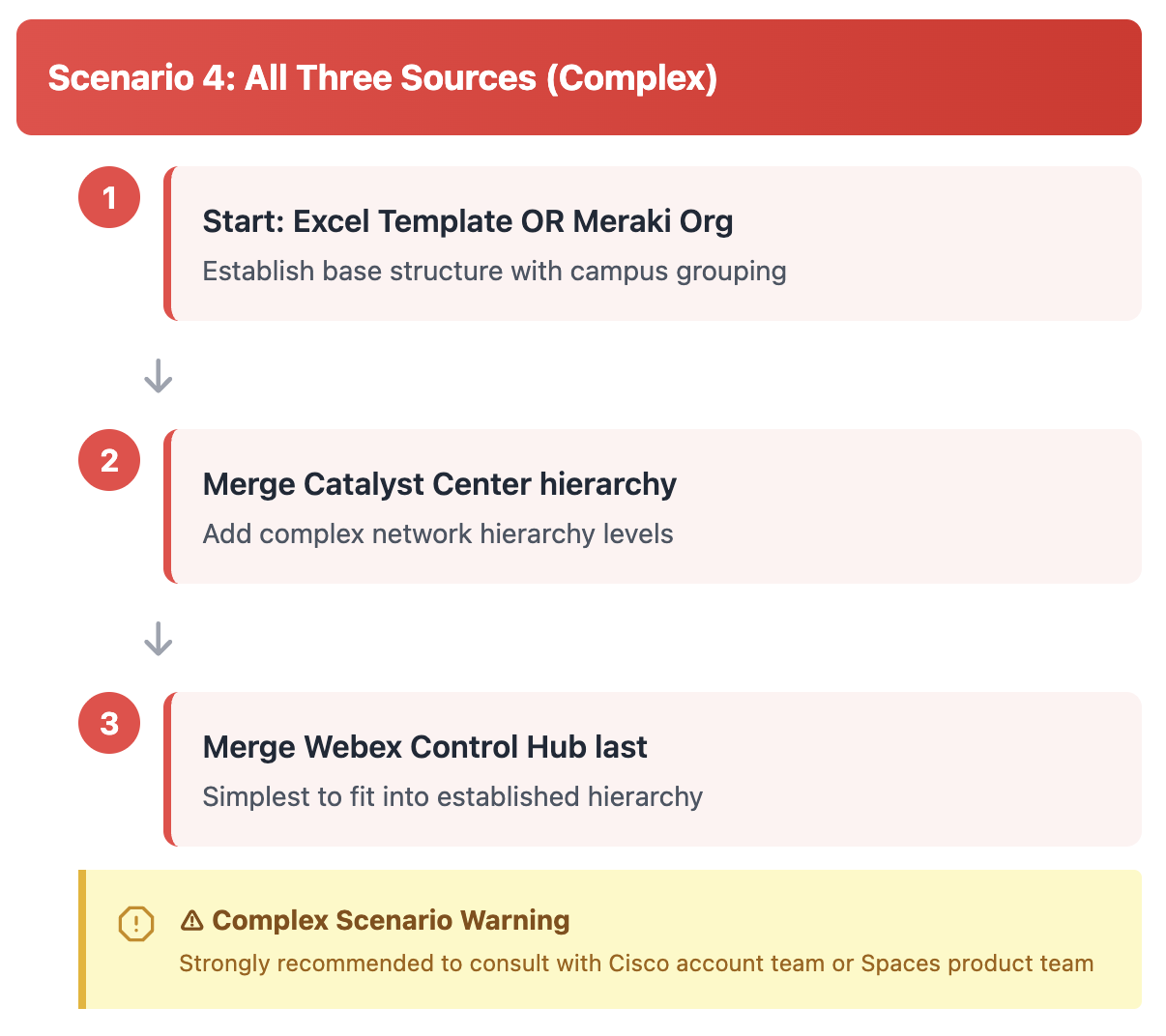
Three Sources
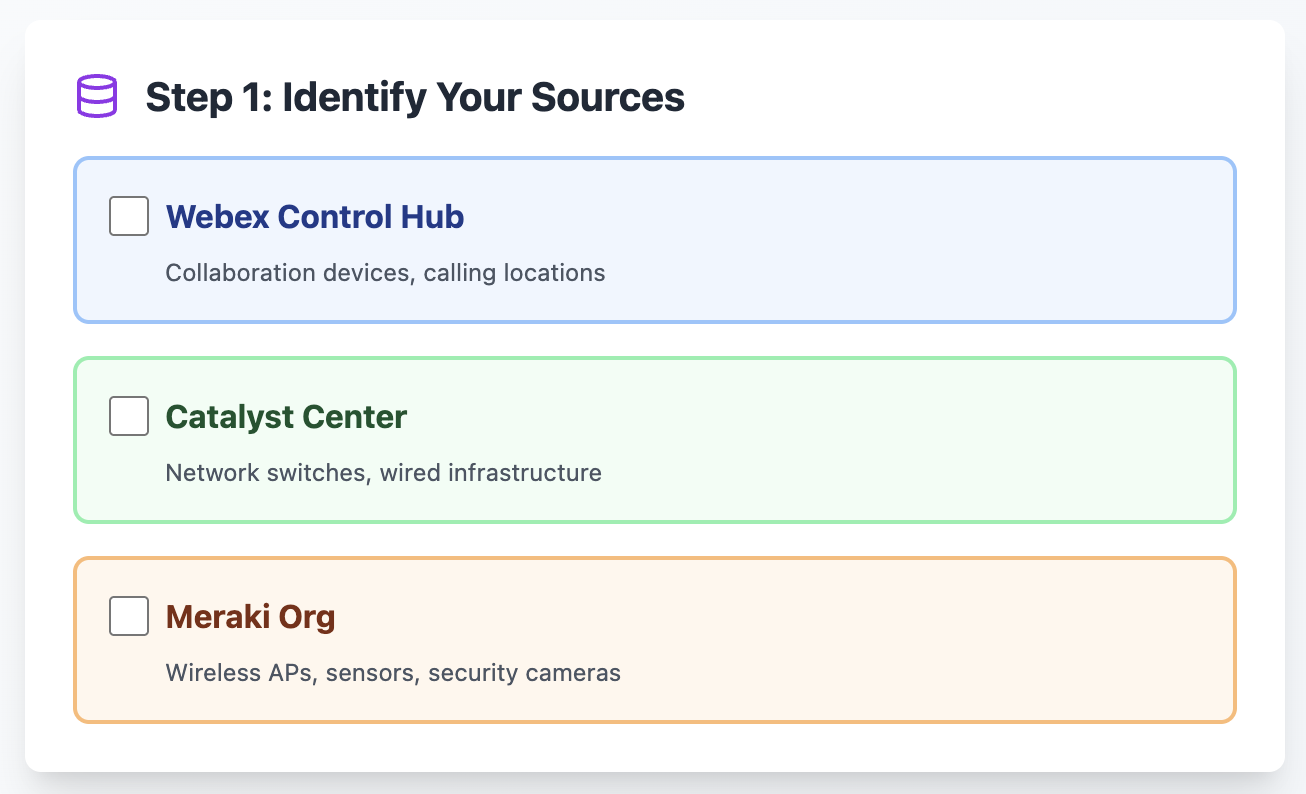
Three sources (for example: Meraki Org for wireless network APs and/or Meraki Things - MT sensors, Catalyst Center for network switches, and Webex Control Hub Org for collaboration devices) is one of the more complex Location Hierarchy merge scenarios. Please proceed with caution and it is highly encouraged to consult your Cisco account team and Cisco Spaces product management for guidance.
First Source
Recommended: Excel Template or Meraki Org
Each of the network hierarchies typically have more complicated hierarchies, so they are recommended for creating the base structure of the Cisco Spaces Location Hierarchy.
If there are two network sources, it is recommended to start with the Meraki Org, then merge/create levels from the (usually more complicated - more levels) Catalyst Center hierarchy. The Meraki Org node itself will need to be the top level node in the hierarchy, and all other levels will be merged/created under it. Merging more complex hierarchies into a Meraki Org hierarchy will cause the Networks/Locations to move lower in the hierarchy (i.e. deeper indentation).
Note: to add a custom business hierarchy and in more complex outcome scenarios (e.g. Campus Wayfinding), it is encouraged to use the Excel Template hierarchy method first.
If using the Excel Template method first, please ensure that the three level limit (e.g. Region, Country, Campus) is compatible with your network hierarchy structure. Additional levels, for example, from Catalyst Center will cause the Location Hierarchy to expand with more levels and deeper indentation. Also, structure it so that all Excel Template locations will match up with the network levels, especially much more complex Catalyst Center hierarchies.
Second Source
Recommended: Catalyst Center
Additional levels, for example, from Catalyst Center will cause the Location Hierarchy to expand with more levels and deeper indentation.
Third Source
Recommended: Webex Control Hub Org
Because Webex Control Hub Locations are “flat”, they are also the easiest to merge into either of the more complex (i.e. more levels) network hierarchies and/or the Excel Template hierarchy method.
Other Less Common Scenarios
Multiple Catalyst Centers
In the case of multiple Catalyst Centers, more than one can be added to a single Cisco Spaces Tenant. It is important to note that the Regions > Campuses > Buildings > Floor nodes (example levels - the hierarchy can have many more nodes/levels) of the Catalyst Center hierarchy from each Catalyst Center cannot overlap. The Region level (for example) and everything lower in the hierarchy of each cannot be mixed with another Catalyst Center hierarchy.
Multiple Meraki Orgs
In the case of multiple Meraki Orgs, more than one can be added to a single Cisco Spaces Tenant. It is important to note that the Org > Network > Floorplan (floors) nodes of the Meraki Dashboard hierarchy from each Meraki Org cannot overlap. The Org level and everything lower in the hierarchy of each cannot be mixed with another Meraki Org hierarchy.
{{details}}
One Meraki Org and Multiple Cisco Spaces Tenants
In the case of a single Meraki Org mirrored across multiple Cisco Spaces Tenants, the initial integration should be added via the Cisco Spaces integration inside the Meraki Dashboard. Additional Cisco Spaces Tenants should be setup using the Meraki API Key Method.
Multiple Cisco Spaces Tenants or Webex Control Hub Orgs
Not supported
The Webex Control Hub Org to Cisco Spaces Tenant integration is a 1:1 integration. A Webex Control Hub can only be integrated with one Cisco Spaces Tenant. Likewise, multiple Webex Control Hub Orgs cannot be integrated into a single Cisco Spaces Tenant.
Meraki Campus Gateway (MCG)
Not supported
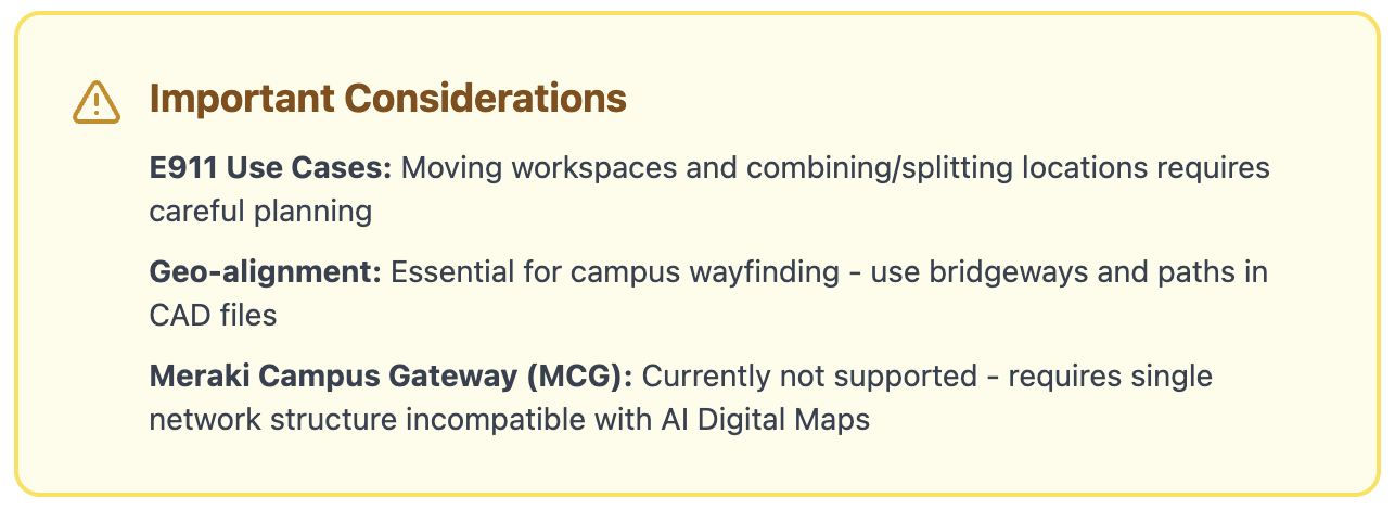
A current pre-requisite for the Meraki Cloud Gateway (MCG) appliance is that all networks and floorplans must be combined into a single Network in Meraki Dashboard. This will result in a single Location (i.e. Building) in Cisco Spaces Dashboard with floors from across the entire campus. This Location Hierarchy structure is incompatible with the AI Digital Maps component of the Spaces OS because CAD floorplans of buildings need to be separated by physical buildings and cannot exist in a single combined Location. Similarly, Control Hub and Catalyst Center Locations and Floors will not be able to merge into the MCG Network structure.
MCG management and restrictions could change in the future. The Cisco Spaces product development team is looking into options to support MCG in the interim. Contact us to discuss your current or planned setup to ensure compatibility for Cisco Spaces outcomes.
Scenario Mapping

FAQs
Will my E911 use cases in Webex Control Hub be affected by changes I need to make to my Locations and Floors?
Yes and no. Moving Workspaces from one Location to another and combining / splitting locations will need to be approached with care. Combining floors (for example: single physical floors that had been split into multiples of that floor to represent “wings” - 3A/3B/3C or 3N/3W/3S/3E) will not impact E911 use cases.
If I have a single Webex Calling Location for an entire region or campus (multiple buildings), can I use Cisco Spaces outcomes?
In order to achieve Cisco Spaces outcomes beyond a single physical building (one AI Digital Map), there may need to be significant changes to the Webex Calling architecture. Having all users and call routing under a single location prevents assigning video endpoints to Meeting Rooms and desk devices to Workstations outside of the single building instance in Cisco Spaces. Separate Locations and their Floors are essential for creating a unified Location Hierarchy.
Are there any specific considerations for Campuses in outcomes?
For example, there are several factors that affect (future/roadmap) Campus Wayfinding and decrease time to process CAD files:
-
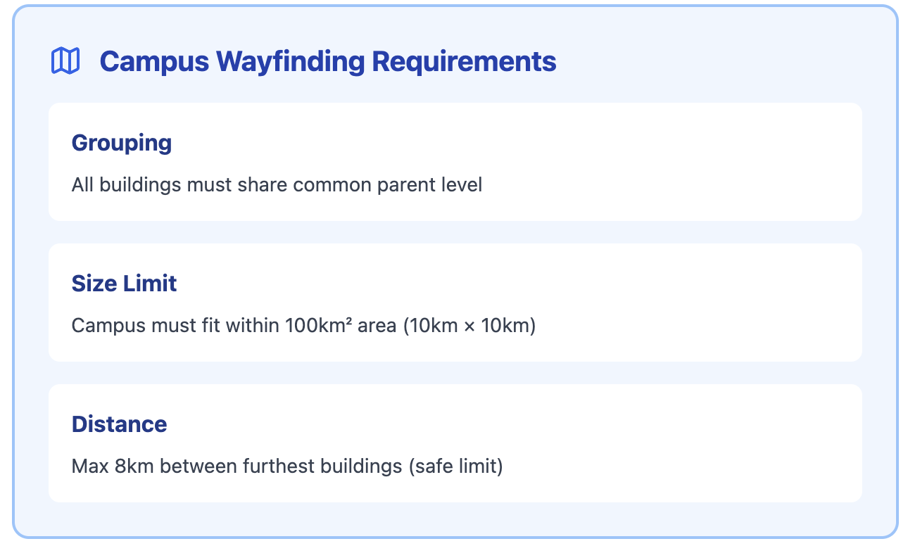
Locations in the Location Hierarchy MUST be grouped under the same common level above the Building level.
-
A group of Buildings (i.e. Campus) MUST fit within a 100km² area (roughly 10km x 10km). To be safe, the distance between the 2 furthest buildings must be no more than 8km.
-
Geo-alignment on the world map is essential. Elements included in the CAD files (e.g. bridgeways, paths, etc.) can help align Buildings to ensure smooth transitions between Buildings in a Campus.
What if my network map floorplan size is past the maximum number of APs that can be assigned to a single floor in Catalyst Center?
General guidance is to include no more than 300 APs on a single network map (floor). If wayfinding and other location services outcomes density requirements or the square footage require splitting the floorplan into smaller sections, there may be different options for structuring the network and floorplans. Please reach out to the Cisco Spaces product management team to consult on the optimal setup.
Caveats and Tips