CISCO VALIDATED
OVERVIEW
With the standard expectation of users to always be connected to the internet no matter where they are, it is paramount that users can be connected securely and seamlessly.
This Cisco validated runbook will look at Captive Portals to onboard customers.
A captive portal is the first touchpoint with your business for customers on Wi-Fi. It provides an opportunity to engage with customers who connect to Wi-Fi, offer relevant information, drive monetization, and potentially acquire customer information. Captive portals enable businesses to choose from multiple authentication mechanisms and deliver targeted experiences based on business rules. They can recognize repeat visitors and deliver customized offers, enhancing customer engagement and loyalty.
SUPPORT AND ONBOARDING
Please follow the link below to find out about the different ways to get support for Cisco Spaces.
PREREQUISITES
This Cisco validated runbook is designed only as a follow on from the Spaces OS Runbook. If you have not completed that runbook yet, please go back and ensure that the deployment has been validated against that before continuing here.
General Prerequisites
Captive Portal requires the following prerequisites met:
-
An active Cisco Spaces account.
-
A Cisco wireless network. Both controller-based (Cisco AireOS or Cisco Catalyst wireless controller) and cloud-based (Cisco Meraki) networks are supported.
-
Add the wireless network to your Cisco Spaces account.
-
For controller-based architecture, the Cisco Spaces Connector must be used.
-
For Cisco Meraki networks, add the Cisco Meraki account to your Cisco Spaces account.
-
-
Wireless Access Points (WAPs) must be in the Cisco Spaces Location Hierarchy. If importing from Catalyst Centre, ensure that WAPs are assigned to floor maps in Catalyst Centre (not just to sites). This is a pre-requisitve to have the WAPs present in Cisco Spaces Location Hierarchy. Without WAPs being present in the Location Hierarchy, clients will not get redirected to the Captive Portal.
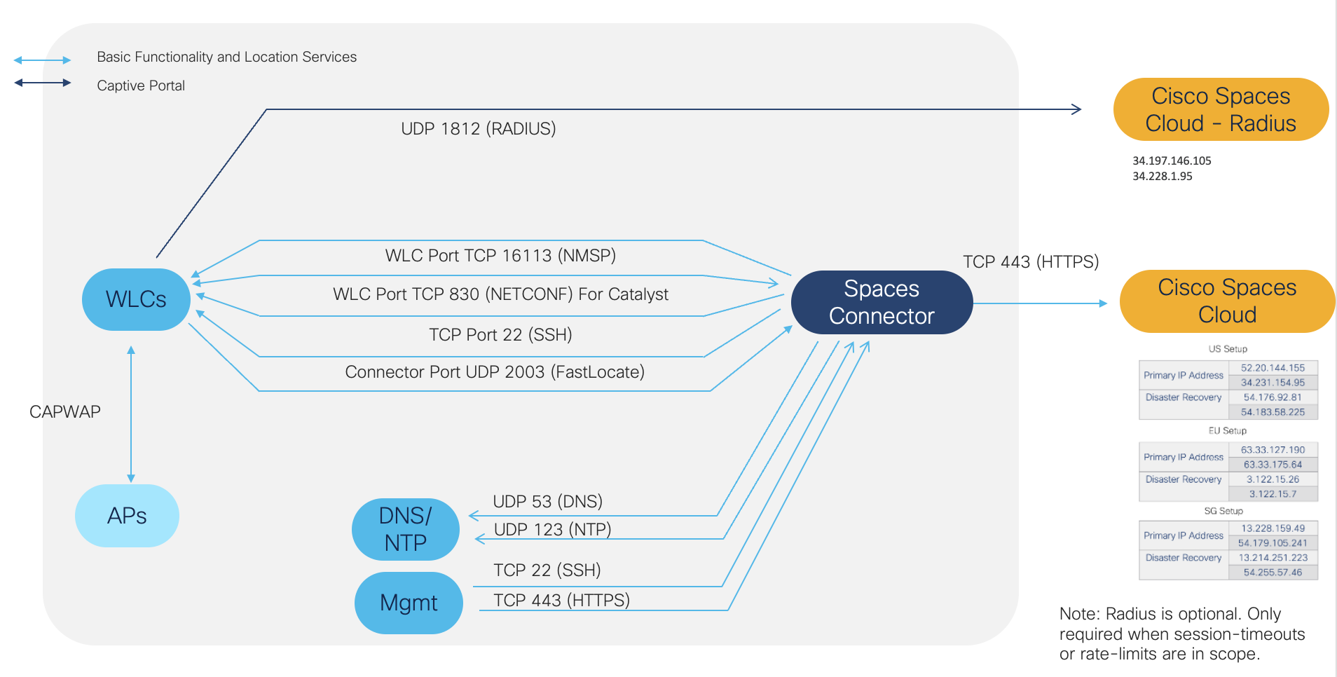
Captive Portal Firewall Port List and Routing
IMPLEMENTATION
At a hight level, the Cisco Spaces' Captive Portal architecture is as follows:
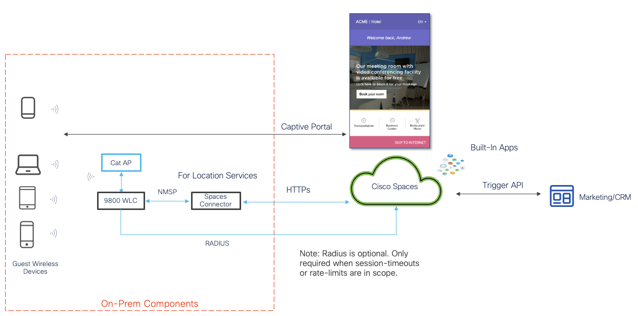
The process of setting up a Captive Portal requires two important tasks of i) Wireless Infrastructure Configuration and subsequently, ii) Captive Portal Configuration.
The Wireless Infrastructure Configuration ensures the underlying network is ready to host a Captive Portal setup. Once the Wireless Infrastructure configuration has been completed, the Captive Portal Configuration steps can commence on Cisco Spaces dashboard.
Wireless Infrastructure Configuration
Setting up Wireless Infrastructure for Captive Portal requires the following steps:
-
Configure webauths parameters
-
Configure ACLs
-
Configure AAA servers
-
Configure SSID
Please refer to the relevant Wireless Infrastructure instructions based on the controller in your network.
Meraki Wireless Infrastructure Configuration
Click the arrow to expand content related to Meraki Wireless Infrastructure Configuration.
Meraki Wireless Infrastructure Configuration
Click here for a video guided demo
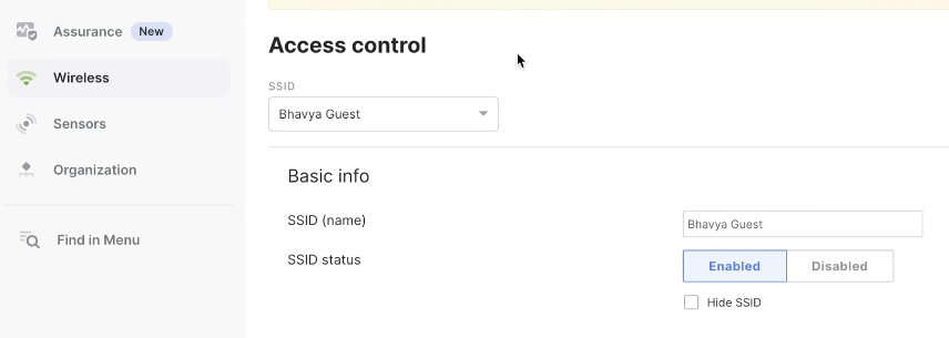
Step 1: Edit / Create SSID in Meraki
This step is needed if a new SSID needs to be created for a Captive Portal, so that it can be imported into Cisco Spaces.
-
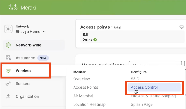
In the Meraki Dashboard, Navigate to the Wireless > Access Control
-
Create or edit the SSID that is needed for Captive Portal access.
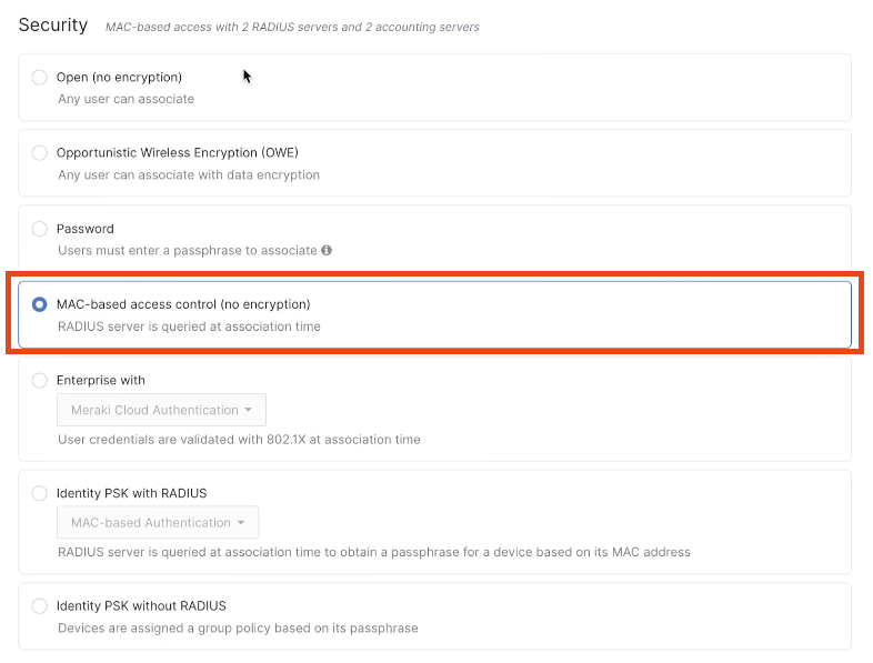
-
In the Security area, choose Mac-based access control (no encryption).
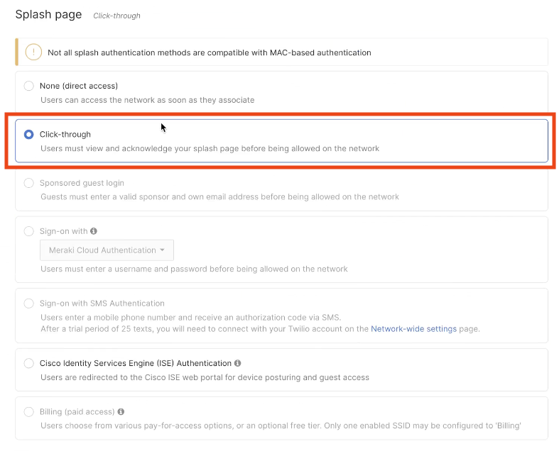
-
In the Splash page area, choose Click-through.
Step 2: Import the SSID in Cisco Spaces
-
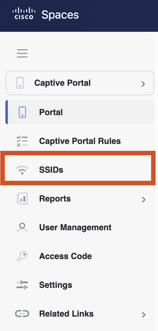
In Cisco Spaces dashboard, navigate to Captive Portals application:
-
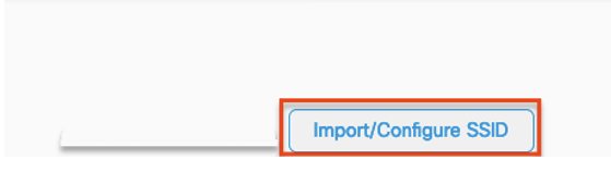
Then: SSID -> Import / Configure SSID -> Meraki
Choose the organization.
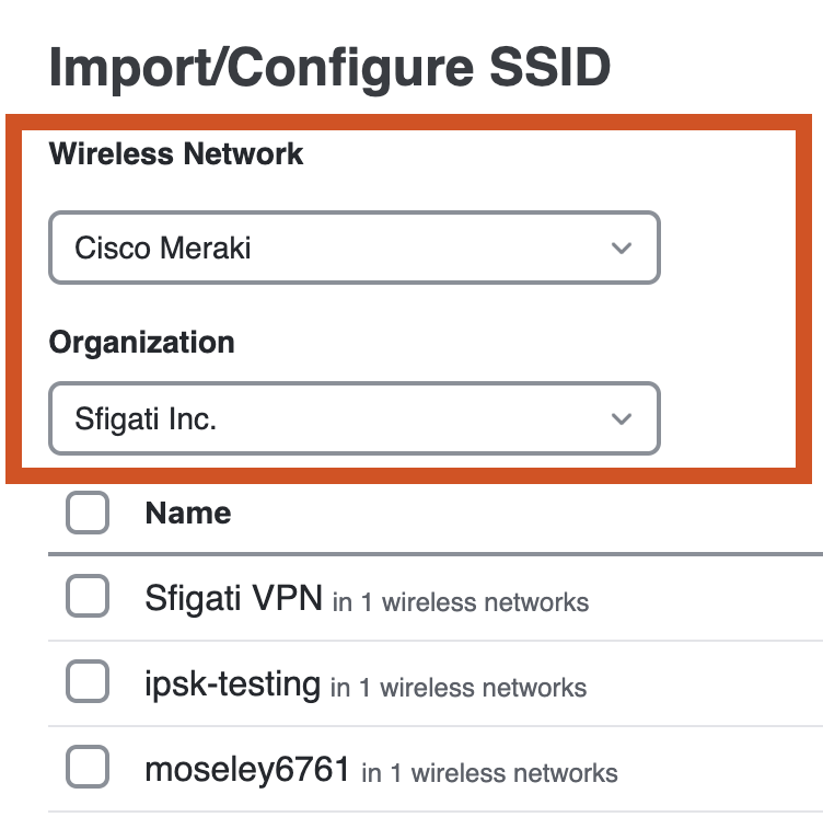
If the sync is not complete yet, you will not see the SSID. In which case, wait until sync is complete and try again to see the SSID. It may take up to 2hrs for the sync to complete.
-
If the synch is completed and SSIDs are visible, choose the SSID and click Import.
-
Once imported, click Configure Manually and choose the appropriate Wireless Infrastructure for relevant instructions. In this case, it will be Cisco Meraki.
-
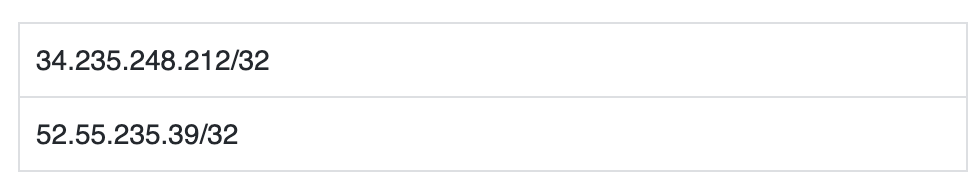
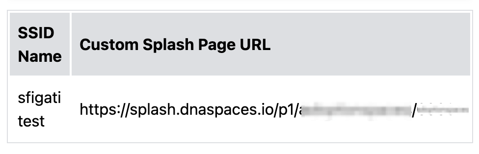
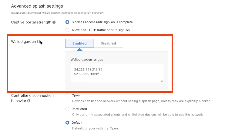
Click the Configure SSID tab and note important information regarding Wall garden and the Custom Splash Page URL. These details will need to be configured on the Meraki dashboard in later steps.
Walled GardenThese two IP addresses will be used as inputs in a later step: 34.235.248.212/32 & 52.55.235.39/32
Splash Page URL
-
Click the Configure Radius Server tab and note details of the Radius authentication and accounting servers for configuration in the following steps.
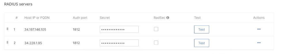
Radius Authentication
|
Host |
34.197.146.105
|
|---|---|
|
Port |
1812 |
|
Secret Key |
************** |
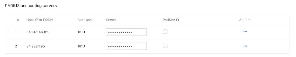
Radius Accounting
|
Host |
34.197.146.105
|
|---|---|
|
Port |
1813 |
|
Secret Key |
************** |
Step 3: Configuration in Meraki
-
In the Meraki dashboard, navigate to Wireless > Access Control Radius servers area, click Add server, and in the fields that appear configure the radius server details for authentication. Add the following servers separately:
-
In the Radius accounting servers area, click Add server, and in the fields that appear configure the radius server details for accounting. Add the following servers separately:
-
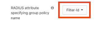
From the "Radius attribute specifying group policy name" drop-down list, choose Filter-Id.
-
Scroll back up to the Advanced splash settings (directly above Radius configuration) and click it. Enter the Walled garden details there using the two IP addresses noted in an earlier step: 34.235.248.212/32 & 52.55.235.39/32
-
Save the changes
-
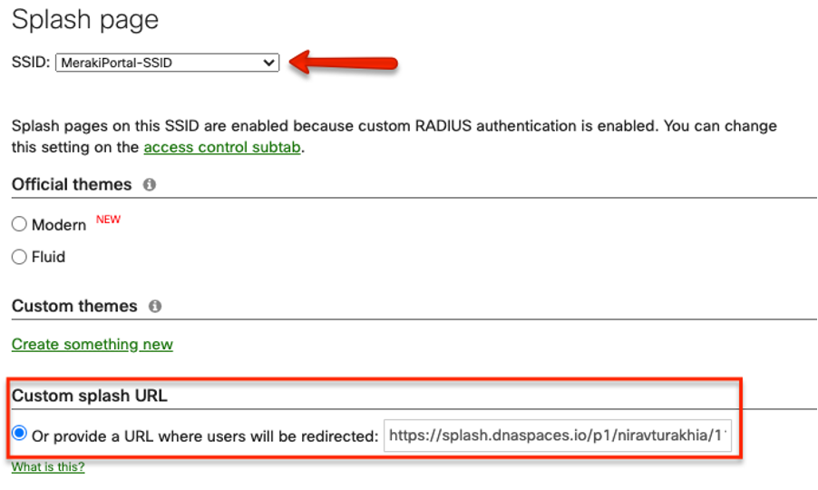
Navigate to Wireless > Configuration > Splash Page. Choose the correct SSID for configuring.
-
In the Custom Splash URL area, choose “Or provide a URL where users will be redirected” and paste the Splash page URL copied earlier from Cisco Spaces.
-
Save the changes.
Step 4: Configuration in Meraki
-
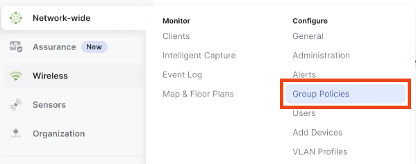
In the Cisco Meraki dashboard, click Network-wide > Group Policies
-
Click Add a Group
-
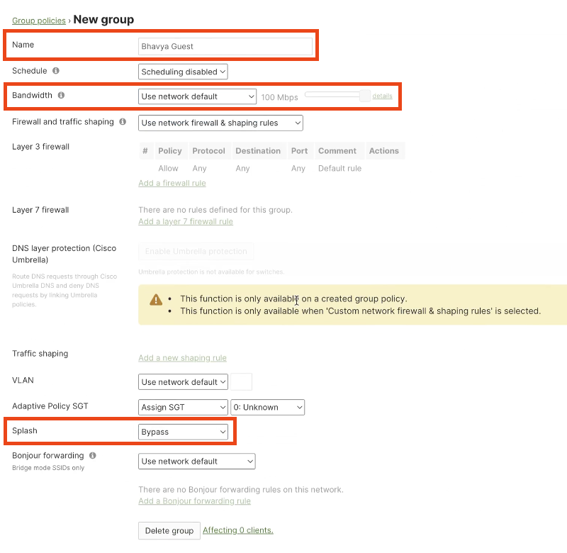
In the New Group window that appears, enter a name for the group. Note this name exactly, since it will be needed in Cisco Spaces rules when provisioning seamless authentication.
You have to configure this name as the policy name in the Cisco Spaces dashboard. If you are specifying the group name as "CaptiveBypass", this policy name will act as the default policy name for all the Captive Portal rules. That is, if you are not specifying a policy name for a Captive Portal rule for which the "Seamlessly Internet Provision" is opted, the policy name "CaptiveBypass" will be applied for that rule.
-
From the Bandwidth drop-down list, choose the required option, and specify the Internet bandwidth to be provisioned for the customers.
-
From the Splash drop-down list, choose Bypass.
-
Save Changes
Catalyst Wireless Infrastructure Configuration
Click the arrow to expand content related to Catalyst Wireless Infrastructure Configuration.
Catalyst Wireless Infrastructure Configuration
For detailed instructions on setting on Cisco Spaces Captive Portal with Catalyst 9800 WLC, please refer to the configuration guide here.
Please note, Catalyst 9800 Wireless Controller must have a trusted certificate installed tied to the virtual int ip/dns entry. If this is not set, clients will get an untrusted server error.
Learn more
If further assistance is needed with the trusted certificate, please raised a TAC case with the Cisco Wireless team.
Click here for a video guided demo
Create the Captive Portal SSID on Cisco Spaces
-
In Cisco Spaces dashboard, navigate to Captive Portals application:
-
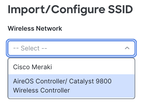
Then: SSID -> Import / Configure SSID -> AireOS Controller / Catalyst 9800 Wireless Controller
Choose the organization.
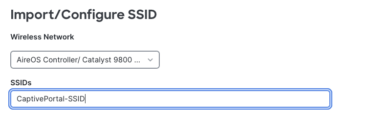
-
Create the SSID that you will use for the Captive Portal and click Add at the bottom.
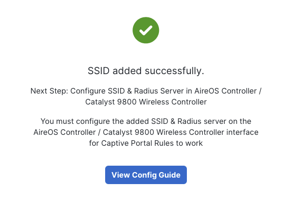
-
Click View Config Guide to access key information needed for next steps.
Get Splash Page URL details
The Splash Page URL details are needed to redirect login to the Splash page. The URL is required to configure WebAuth paramaters in a later step.
-
After clicking View Config Guide (from the previous step), navigate to Catalyst 9800 Wireless Controllers -> Configure SSID → Creating the Access Control List.
-
Under the section Creating the Access Control List, scroll down to Step 2g. and the Cisco Spaces splash URL for your tenant will be there. It will appear as:
https://splash.dnaspaces.io/**/*******
If you are using the EMEA portal, the splash page URL will appear as https://splash.dnaspaces.eu/**/***** or https://splash.ciscospaces.sg/**/**** for APAC portal
-
Make a note of this URL to set in the WebAuth parameter later.
Create the Access Control List (if required)
By default, the 9800 creates hardcoded pre-auth ACLs when you setup a web-auth WLAN. These hardcoded ACLs allow DHCP, DNS, and traffic to the external web auth server. All the rest is redirected like any http traffic.
However, if you need to allow specific non-HTTP traffic type through, you can configure a pre-auth ACL. You would then need to imitate the content of the existing hardcoded pre-auth ACL and augment it to your needs. Please refer to the ACL configuration guide.
Create the URL Filters List
Pre-authentication ACL is used in web authentication to allow certain types of traffic before the authentication is complete. This allows the clients limited access to particular network resources before authentication.
-
Log into Catalyst 9800 Wireless Controller.
-
Create the ACL by adding URL filters.
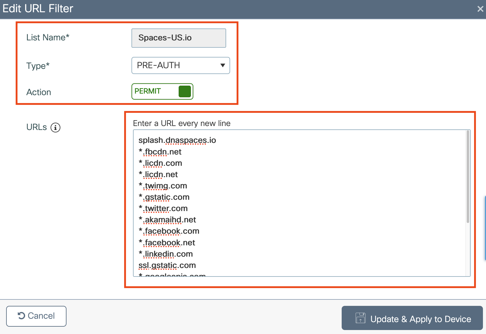
a. Choose Configuration > Security > URL Filters.
b. In the URL Filters window, click Add.
c. In the List Name field, enter the list name.
d. Keep Type as PRE-AUTH
e. Change the status of Action to Permit.
f. In the URLs field, enter the URL splash.dnaspaces.io (or splash.dnaspaces.eu if you are using the EMEA portal; or splash.ciscospaces.sg or for APAC portal)g. In addition to the splash domain configured in step f., add the following domains if you want to enable social authentication for the Captive Portal:
*.fbcdn.net
*.licdn.com
*.licdn.net
*.twimg.com
*.gstatic.com
*.twitter.com
*.akamaihd.net
*.facebook.com
*.facebook.net
*.linkedin.com
ssl.gstatic.com
*.googleapis.com
static.licdn.com
*.accounts.google.com
*.connect.facebook.net
oauth.googleusercontent.comh. Click Update & Apply to Device
Captive Portal - when to use a RADIUS server?
The SSID can be configured to use a RADIUS Server or without it. There are some differences in configuration depending on whether RADIUS is used or not. Both scenarios will be covered in the following sections.
If the Session Duration, Bandwidth Limit, or Seamlessly Provision Internet is configured in the Actions section of the Cisco Spaces Captive Portal Rule configuration, the SSID needs to be configured with a RADIUS Server, otherwise, there is no need to use the RADIUS Server. All kinds of portals on Spaces are supported on both configurations.
Before getting into specific RADIUS / non-RADIUS configurations, ensure base settings like virtual IPs and trustpoint certificate are correct in the Global Web Auth Parameter.
Configure Global Web Auth Parameter
Configure the Global Web Auth Parameter to ensure the default base settings are correct.
-
Navigate to Configuration > Security > Web Auth, Click the ‘global’ parameter name to edit settings.
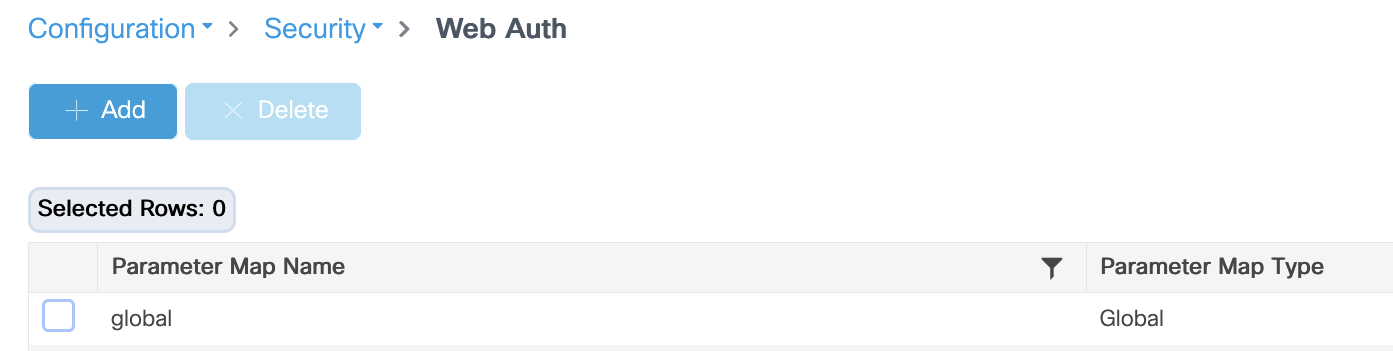
-
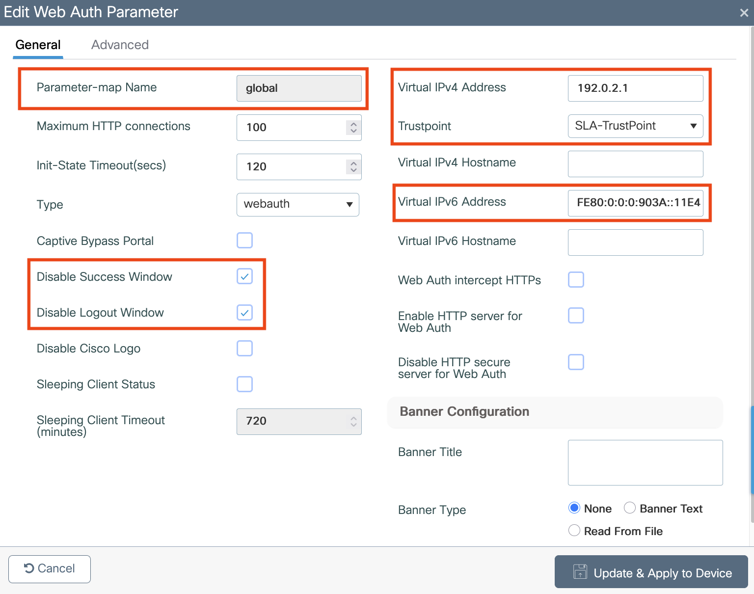
Ensure both IPv4 and IPv6 are present with the default addresses.
Important: Ensure that both Virtual IPv4 and IPv6 addresses are configured in the global web auth parameter map. If the Virtual IPv6 is not configured, the clients are sometimes redirected to the internal portal instead of the configured Spaces portal. This is why a Virtual IP must always be configured.
IPv4: 192.0.2.1 can be configured as Virtual IPv4
IPv6: FE80:0:0:0:903A::11E4 can be configured as the Virtual IPv6.
There are little to no reasons to use other IPs than those.
-
Catalyst 9800 Wireless Controller must have a signed trusted certificate installed tied to the virtual int ip/dns entry. If this is not set, clients will get an untrusted server error. For information about certificates on Catalyst 9800, refer to https://www.cisco.com/c/en/us/support/docs/wireless/catalyst-9800-series-wireless-controllers/213917-generate-csr-for-third-party-certificate.html#anc5
Note: In some cases, a trusted and signed certificate provider does not accept private IP address - such as the default 192.0.2.1. For such cases, please refer to the workaround in the FAQ section: What if my certificate authority won’t issue a certificate for the Catalyst 9800’s virtual IP?
-
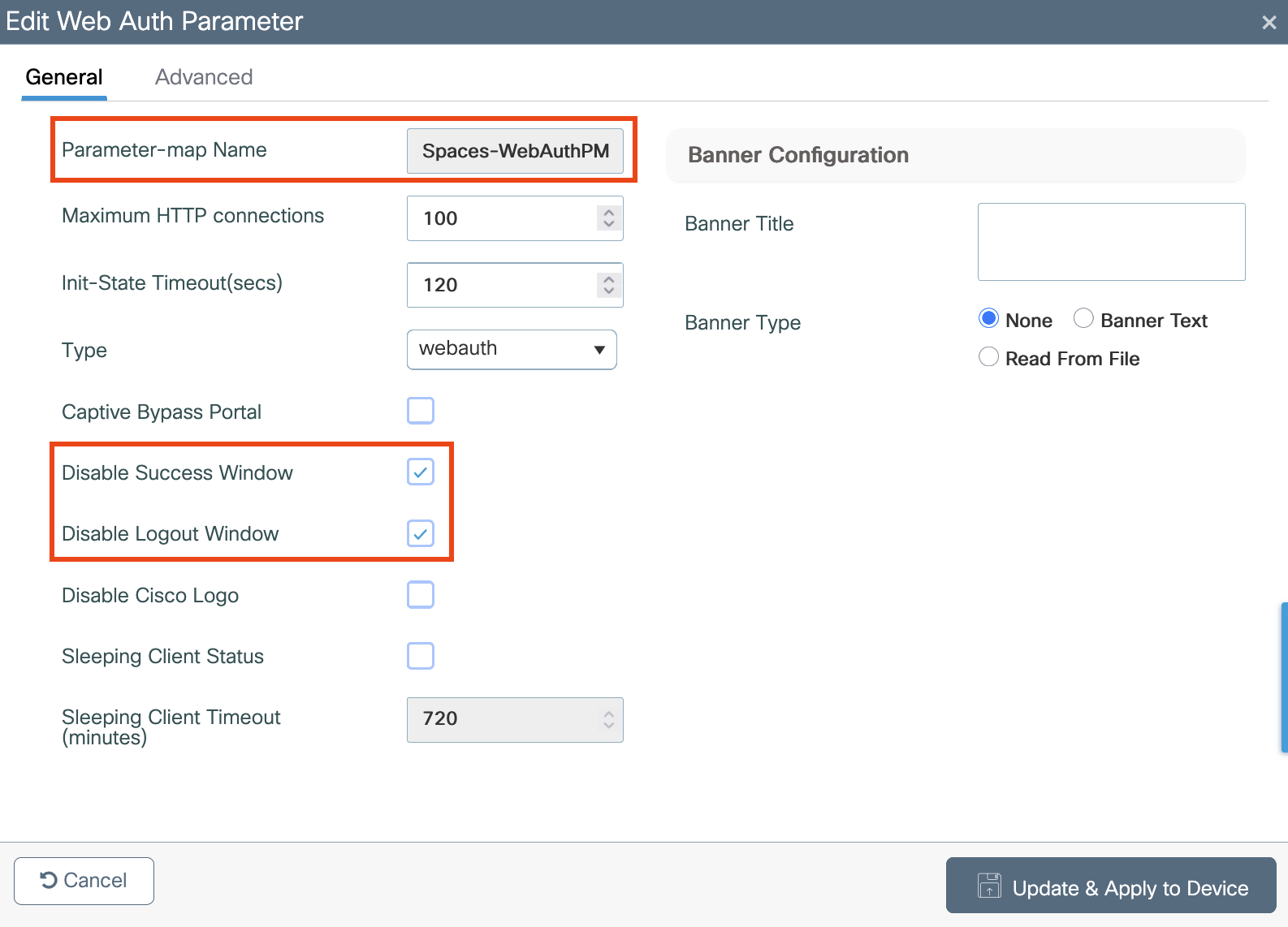
Check the Disable Success Window and Disable Logout Window checkboxes (otherwise the Captive Portal will redirect to the local WLC version)
-
Click Update & Apply to Device to save changes.
Configuring Captive Portal without RADIUS Server
Create the Web Auth Parameter (without RADIUS Server on Cisco Spaces)
A parameter map for web-based authentication sets parameters that can be applied to subscriber sessions during authentication. If you do not create a parameter map, the policy uses default parameters.
To create the Web Auth Parameter Map , perform the following steps:
-
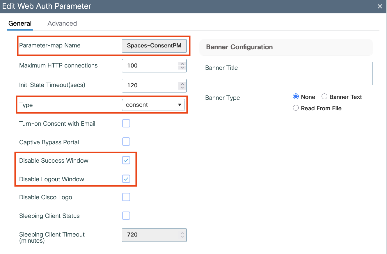
Navigate to Configuration > Security > Web Auth, Click +Add to create a new parameter map. In the window that pops-up configure the parameter map name, and select Consent as the type and check the Disable Success Window and Disable Logout Window checkboxes (otherwise the Captive Portal will redirect to the local WLC version).
-
Still in the Web Auth Parameter settings, navigate to the Advanced tab, and enter the Redirect for log-in URL, Append for AP MAC Address, Append for Client MAC Address, Append for WLAN SSID and portal IPv4 Address as follows and then click Update & Apply to Device.
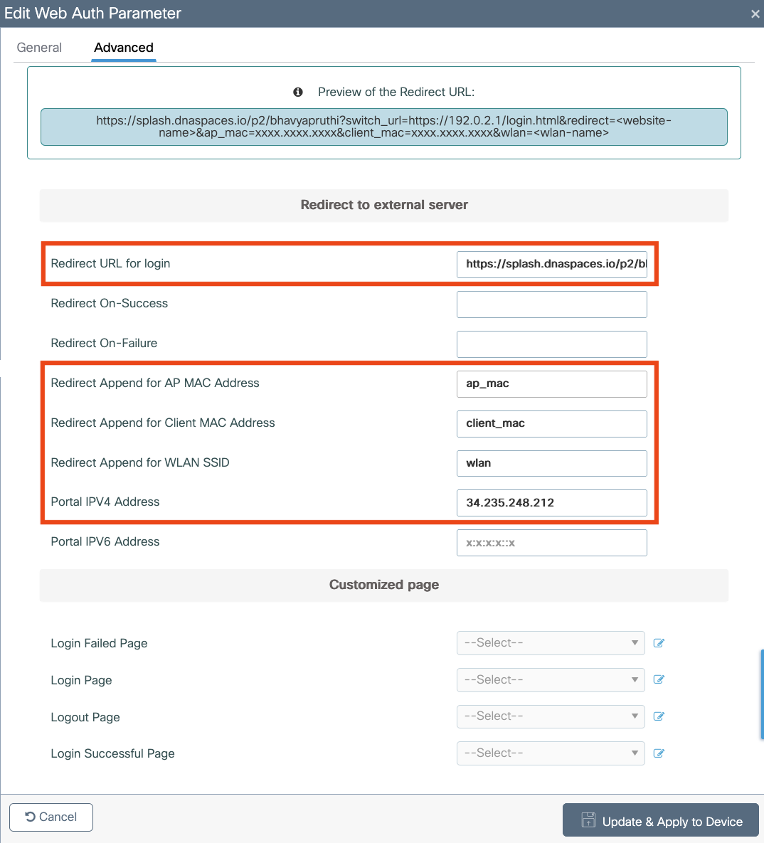
a. Redirect URL for Log-in = <Specific URL for the customer tenant goes here> (refer to Get Splash Page URL details section)
b. Redirect Append for AP MAC Address = ap_mac
c. Redirect Append for Client MAC Address = client_mac
d. Redirect Append for WLAN SSID = wlan
e. Portal IPV4 Address = 34.235.248.212 (please perform an nslookup to the appropriate domain - e.g. splash.dnaspaces.io and use one of the values. Alternatively, refer to table below)
Please consult the table below to work out the correct Portal IPV4 Address to use in Step 2e based on your Cisco Spaces tenant domain. Use only one IP address entry for Step 2e.
|
|
Tenant Domain |
|
|---|---|---|
|
Global (.io) |
splash.dnaspaces.io
|
splash.ciscospaces.io
|
|
EMEA (.eu) |
splash.dnaspaces.eu
|
splash.ciscospaces.eu
|
|
APAC (.sg) |
N/A |
splash.ciscospaces.sg
|
f. Click Update & Apply
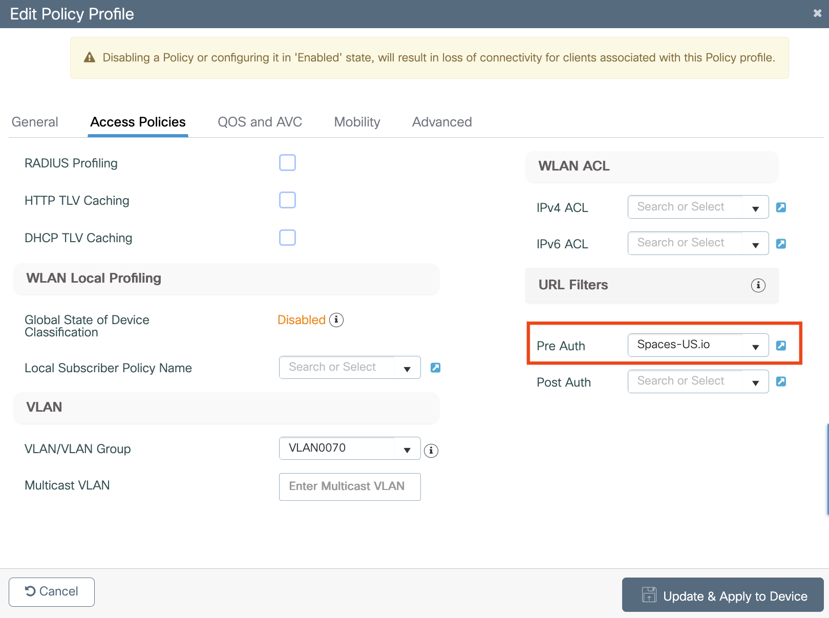
Configure Policy Profile on the 9800 Controller
Policy profile contains policy to be associated with the WLAN. It specifies the settings for client VLAN, URL filters, session and idle timeout settings and so on.
-
Navigate to Configuration > Tags & Profiles > Policy and use the default policy, or create a new Policy Profile. Alternatively, clone the default-policy-profile to customise settings by clicking the checkbox on the left-hand side and then clicking Clone.
-
In the Access Policies tab, configure the client VLAN and add the URL Filters (created previously in Create the URL Filters List).
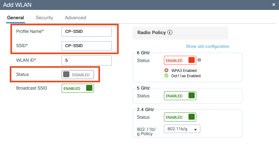
Create the SSID on the 9800 Controller
-
Choose Configuration > Tags and Profiles > WLANs.
-
Click Add.
-
On the General tab, in the Profile Name field, enter the profile name.
-
In the SSID field, enter the Captive Portal SSID name (ensuring that it matches exactly the Captive Portal SSID created in Cisco Spaces).
Important: The SSID entered in this step much match exactly the SSID created in ‘Create the Captive Portal SSID’ step. The SSID in the Controller and Cisco Spaces must match exactly (case-sensitive).
-
Set the status as Enabled.
-
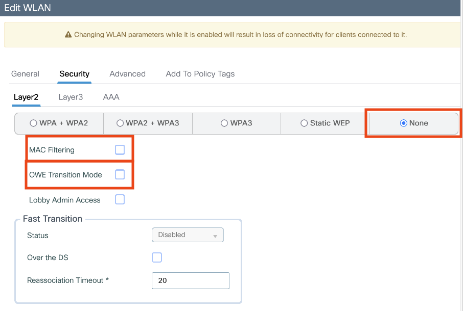
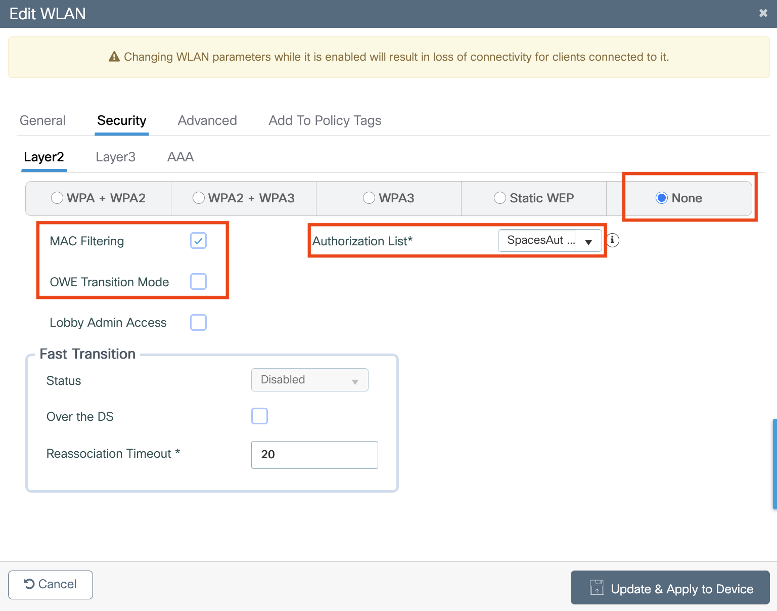
Click the Security tab, and then click the Layer2 tab.
-
From the Layer 2 Security Mode drop-down list, choose None.
-
Ensure MAC Filtering is unchecked
-
Uncheck OWE Transition Mode
-
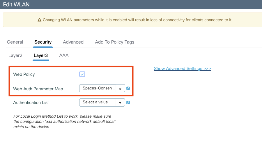
Click the Layer3 tab.
-
Check the Web Policy check box.
-
From the WebAuth Parameter Map drop-down list, choose the Web Auth Parameter Map created previously (in section Create the Web Auth Parameter (without RADIUS Server on Cisco Spaces)).
-
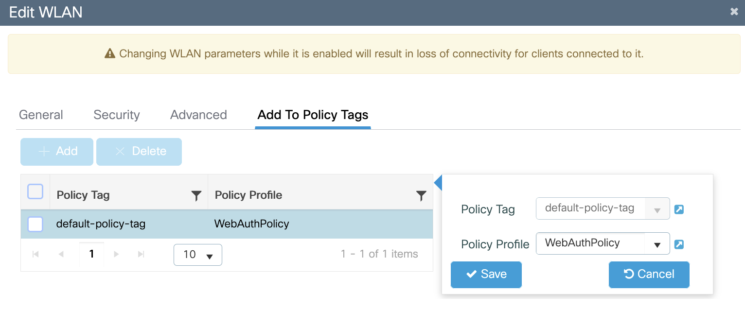
Click on the Add to Policy Tags tab
-
Link the Policy Tag with the Policy Profile
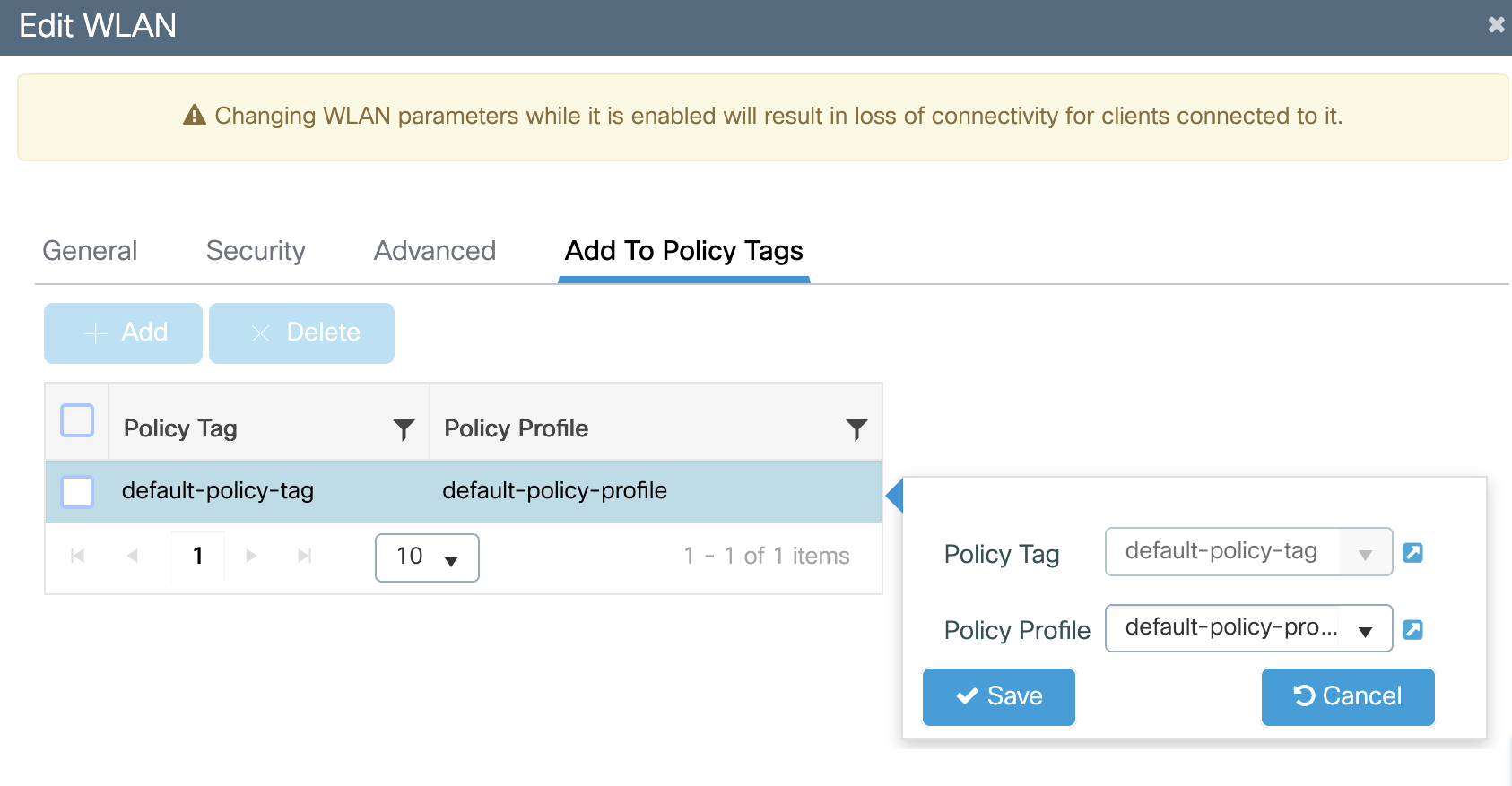
-
Click Save & Apply to Device.
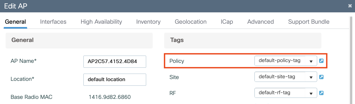
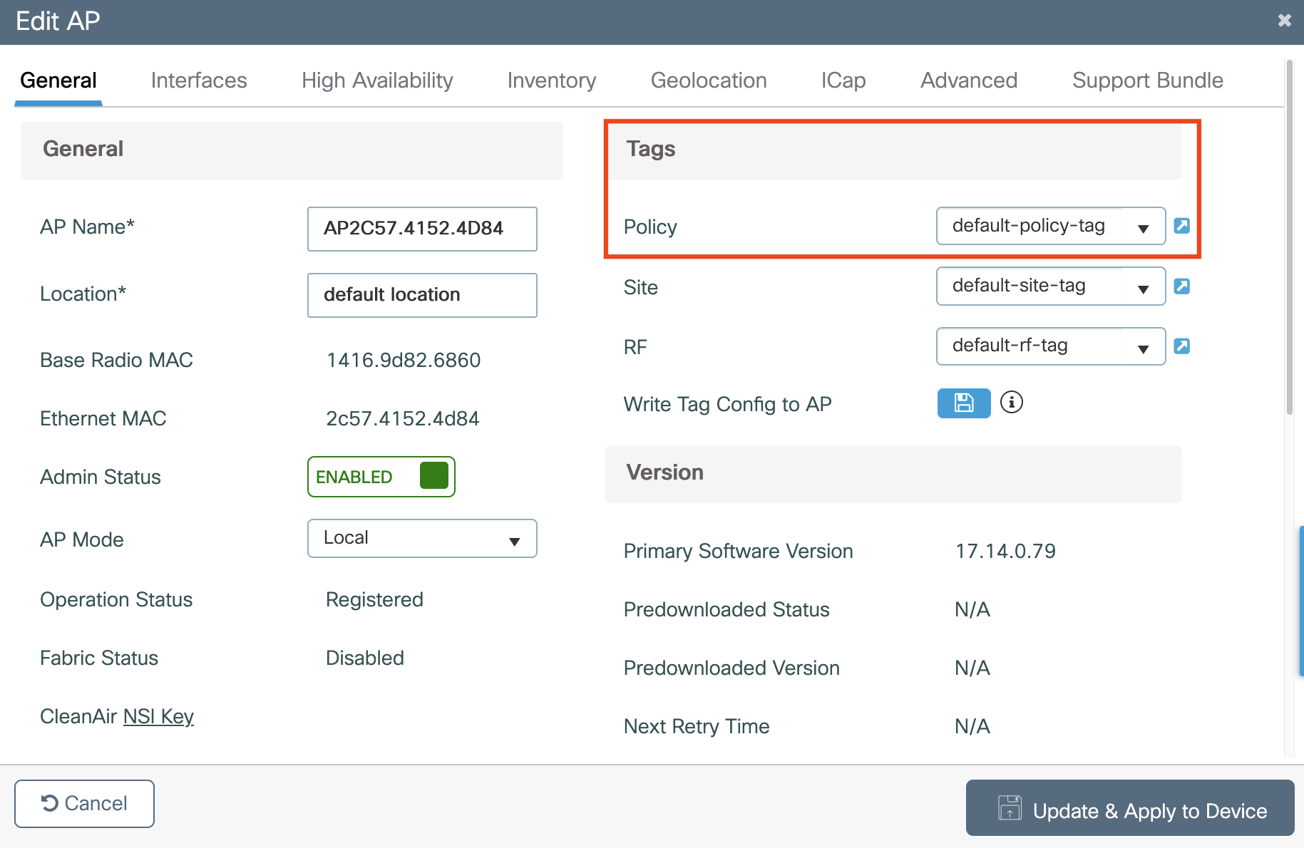
Apply Policy Tag to the AP
The Policy Tag configured in the previous step should be applied to the AP to broadcast the SSID.
-
Navigate to Configuration > Wireless > Access Points
-
Select the AP in question and add the Policy Tag
Important: This causes the AP to restart its CAPWAP tunnel and join back to the 9800 controller
Configuring Captive Portal with RADIUS Server
Create the Web Auth Parameter Map (with RADIUS Server on Cisco Spaces)
A parameter map for web-based authentication sets parameters that can be applied to subscriber sessions during authentication. If you do not create a parameter map, the policy uses default parameters.
To create the Web Auth Parameter Map, perform the following steps:
-
Navigate to Configuration > Security > Web Auth, Click +Add to create a new parameter map. In the window that pops-up configure the parameter map name, and select Webauth as the type and check the Disable Success Window and Disable Logout Window checkboxes (otherwise the Captive Portal will redirect to the local WLC version).
-
Still in the Web Auth Parameter, navigate to the Advanced tab, and enter the Redirect for log-in URL, Append for AP MAC Address, Append for Client MAC Address, Append for WLAN SSID and portal IPv4 Address as follows and then click Update & Apply to Device.
a. Redirect for Log-in = <Specific URL for the customer tenant goes here> (refer to Get Splash Page URL details section)
b. Redirect Append for AP MAC Address = ap_mac
c. Redirect Append for Client MAC Address = client_mac
d. Redirect Append for WLAN SSID = wlan
e. Portal IPV4 Address = 34.235.248.212 (please perform an nslookup to the appropriate domain - e.g. splash.dnaspaces.io and use one of the values. Alternatively, refer to table below)
Please consult the table below to work out the correct Portal IPV4 Address to use in Step 2e based on your Cisco Spaces tenant domain. Use only one IP address entry for Step 2e.
|
|
Tenant Domain |
|
|---|---|---|
|
Global (.io) |
splash.dnaspaces.io
|
splash.ciscospaces.io
|
|
EMEA (.eu) |
splash.dnaspaces.eu
|
splash.ciscospaces.eu
|
|
APAC (.sg) |
N/A |
splash.ciscospaces.sg
|
f. Click Update & Apply
Configure Radius Server
To provide an additional layer of security for your portal, the Cisco Spaces supports radius-authentication for the internet provisioning on the captive portals.
As part of the Radius AAA configuration, Radius Authentication and Authorization servers will be set up.
Radius Accounting servers are not required for Captive Portals and should not be configured
-
Log into Catalyst 9800 Wireless Controller. Cisco Spaces acts as the RADIUS server for user authentication and it can respond to two IP addresses.
-
Configure the RADIUS server.
We highly recommend to use RADIUS authentication for captive portals. The following features work only if you configure RADIUS authentication.
a. Seamless Internet Provisioning.
b. Extended session duration.
c. Deny Internet.
-
Choose Configuration > Security > AAA.
-
In the Authentication Authorization and Accounting window, click the Servers/Groups tab.
-
Choose Radius > Servers, and click Add.
-
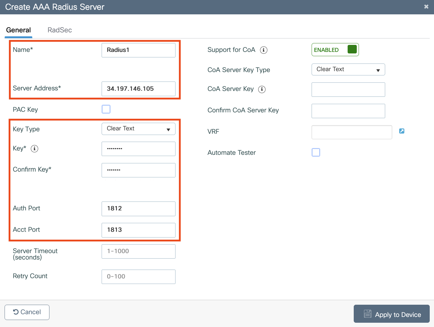
In the Name field, enter a name for the radius server.
-
In the IPv4 / IPv6 Server Address field, enter the radius server address.
Radius Servers
Only Cisco Spaces RADIUS servers can be configured. The servers are listed below.
|
Host |
34.197.146.105
|
|---|---|
|
Port |
1812 |
|
Secret Key |
************** [A customer specific key has to be sourced from the Cisco Spaces dashboard Captive Portal app. See below] |
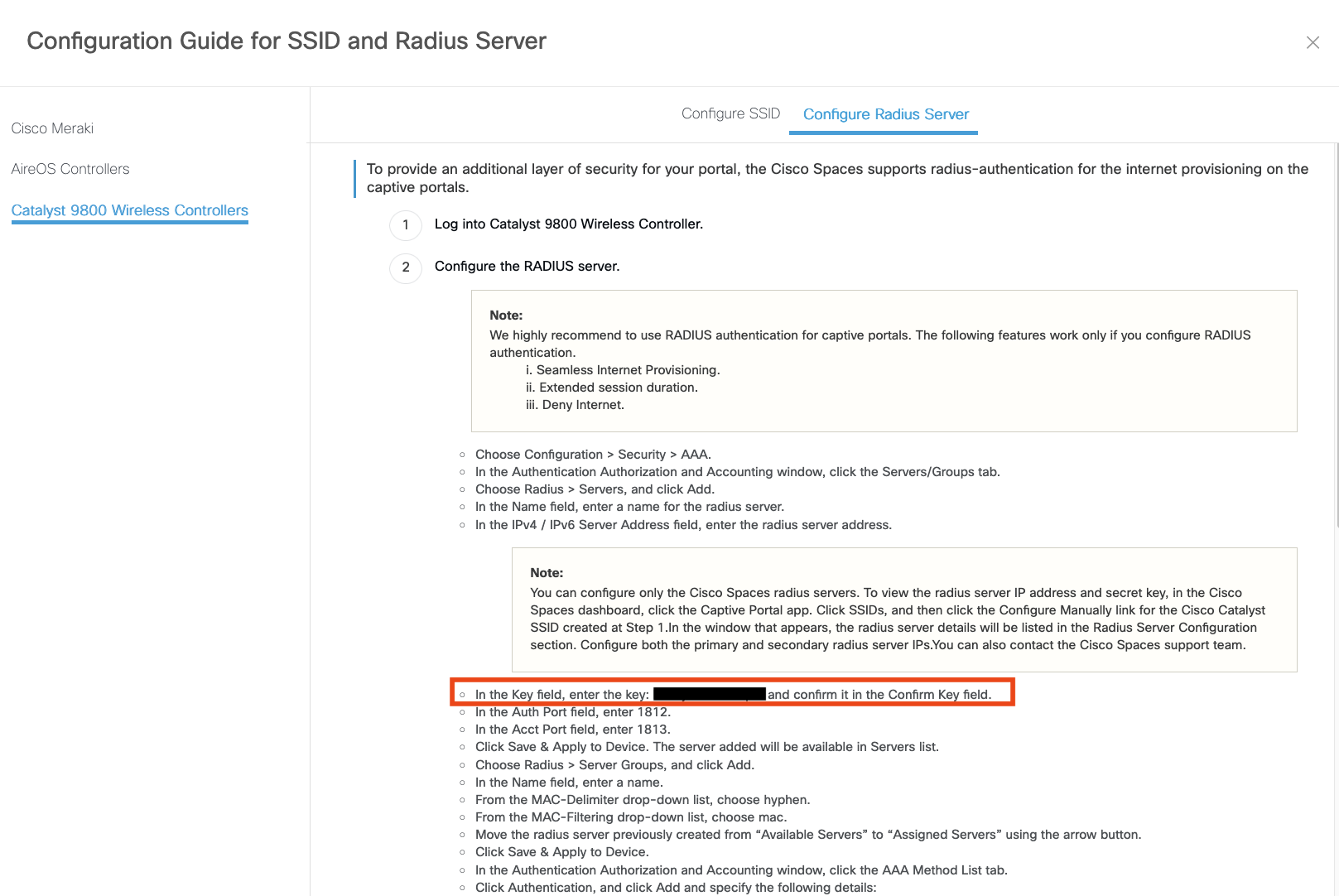
To view the RADIUS server Secret Key, click the Captive Portal app in Cisco Spaces dashboard. Click SSIDs, and then click the Configure Manually link for the Cisco Catalyst SSID. In the window that appears, click the Configure Radius Server tab and the Key field password will be there. Tip: Search for “Key field” in the window.
-
In the Key field, enter the key: ************* and confirm it in the Confirm Key field.
-
In the Auth Port field, enter 1812.
-
In the Acct Port field, enter 1813.
-
Click Save & Apply to Device. The server added will be available in Servers list.
-
Repeat step 5. if a second Radius server is desired, otherwise proceed to creating a Server Group in the next step.
-
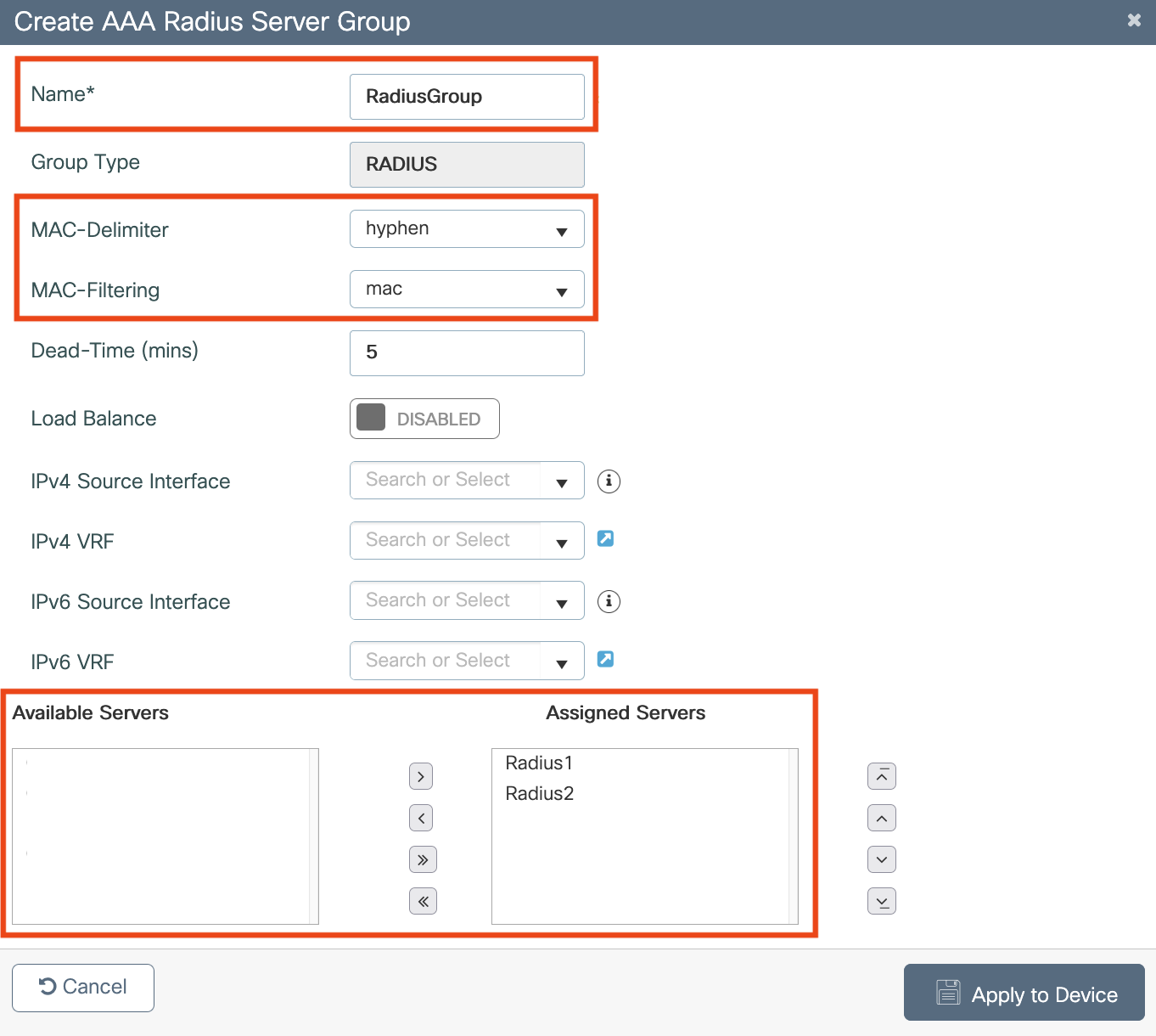
Choose Radius > Server Groups, and click Add.
-
In the Name field, enter a name.
-
From the MAC-Delimiter drop-down list, choose hyphen.
-
From the MAC-Filtering drop-down list, choose mac.
-
Move the radius server previously created from “Available Servers” to “Assigned Servers” using the arrow button.
-
Click Save & Apply to Device.
-
In the Authentication Authorization and Accounting window, click the AAA Method List tab.
-
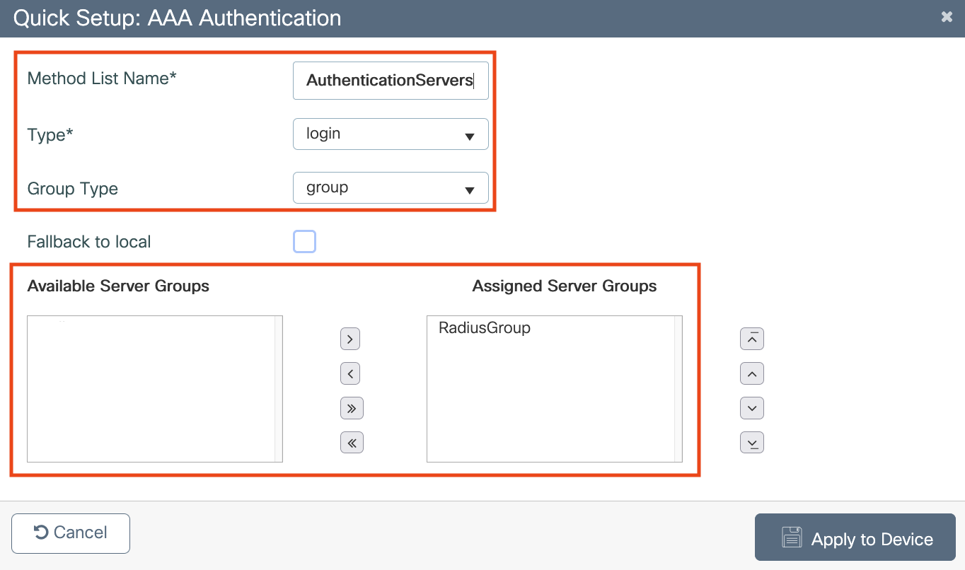
Click Authentication, and click Add and specify the following details:
-
In the Method List Name field, enter the method list name.
-
From the Type drop-down list, choose Login
-
From the Group Type drop-down list, choose Group.
-
Move the server group created earlier from Available Server Groups to Assigned Servers Groups, and click Save & Apply to Device.
-
-
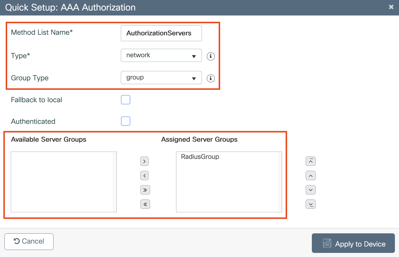
On the AAA Method List tab, click Authorization, and click Add, and specify the following details:
-
In the Method List Name field, enter the method list name.
-
From the Type drop-down list, choose Network.
-
From the Group Type drop-down list, choose group.
-
Move the server group previously created (point 12. to point 17.) from Available Servers to Assigned Servers using the arrow button, and click Save & Apply to Device.
-
As mentioned previously, Radius Accounting servers are not required for Captive Portals and should not be configured.
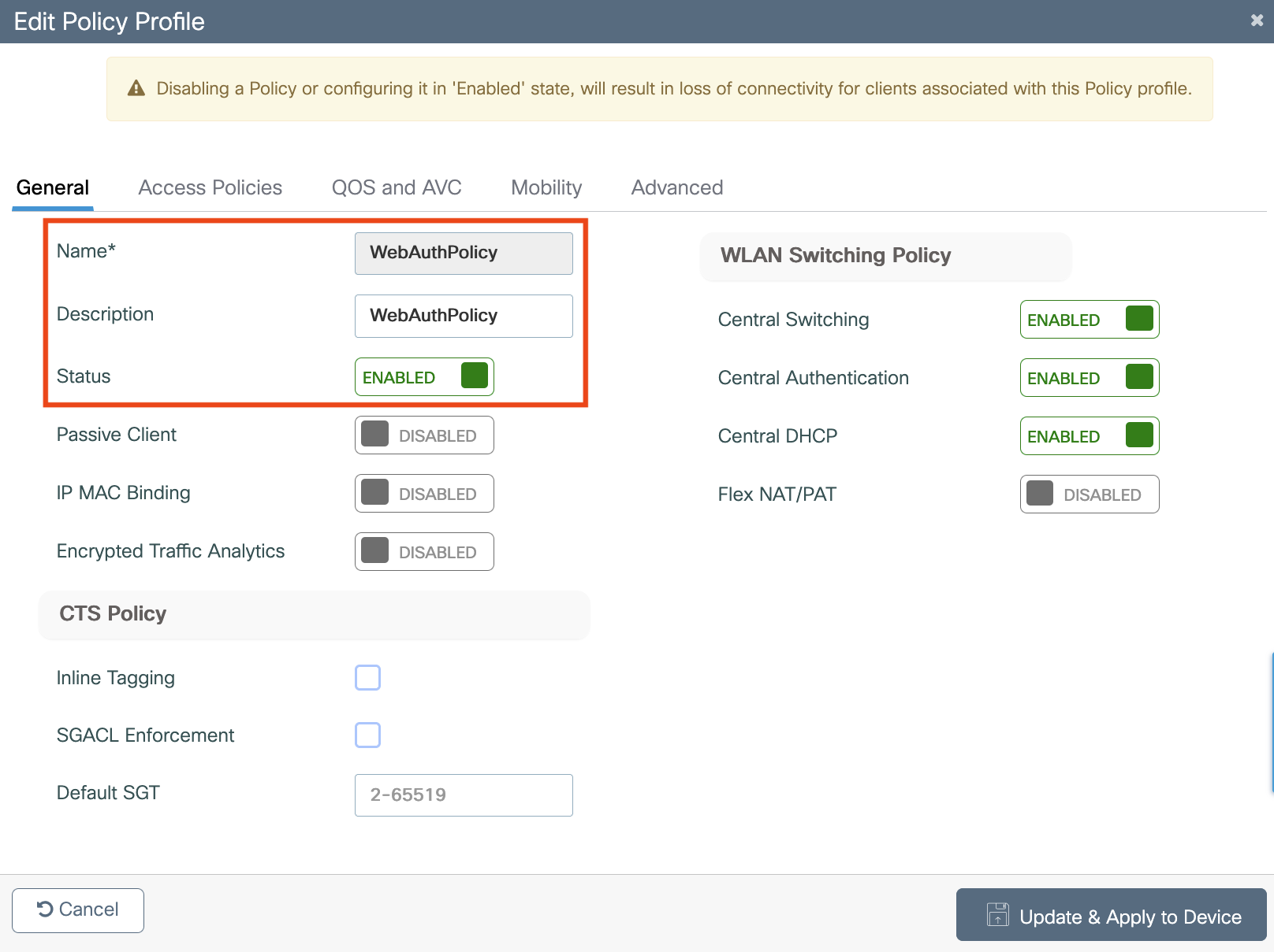
Configure Policy Profile on the 9800 Controller
Policy profile contains policy to be associated with the WLAN. It specifies the settings for client VLAN, URL filters, session and idle timeout settings and so on.
-
Navigate to Configuration > Tags & Profiles > Policy and create a new Policy Profile or use the default Policy Profile.
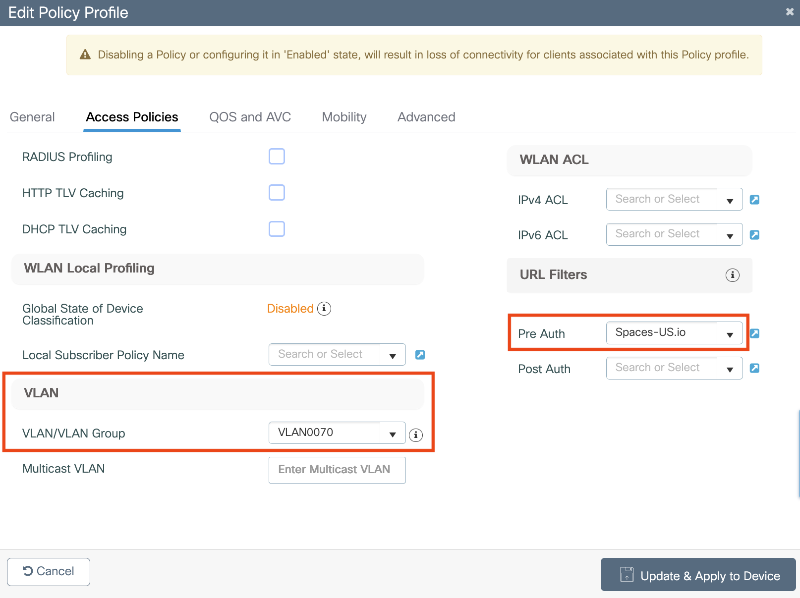
-
In the Access Policies tab, configure the client VLAN and add the URL filter.
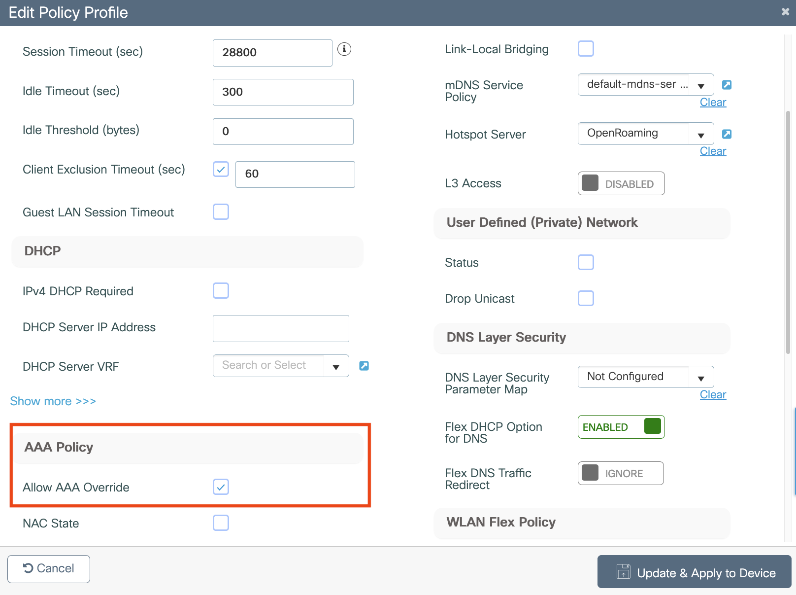
-
In the Advanced tab, in the AAA Policy area, check the Allow AAA Override check box
-
Click Update & Apply to Device.
Create the SSID
-
Choose Configuration > Tags and Profiles > WLANs.
-
Click Add.
-
On the General tab, in the Profile Name field, enter the profile name.
-
In the SSID field, enter the Captive Portal SSID name (ensuring that it matches exactly the Captive Portal SSID created in Cisco Spaces).
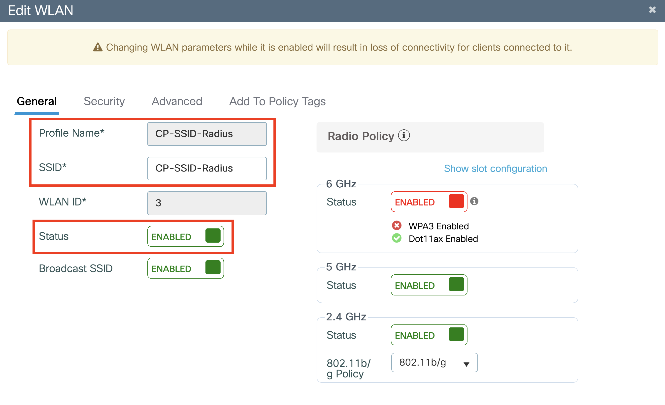
Important: The SSID entered in this step much match exactly the SSID created in ‘Create the Captive Portal SSID’ step. The SSID in the Controller and Cisco Spaces must match exactly (case-sensitive).
-
Set the status as Enabled.
-
Click the Security tab, and then click the Layer2 tab.
-
From the Layer 2 Security Mode drop-down list, choose None.
-
Enable MAC Filtering, uncheck OWE Transition Mode and add the Authorization List
-
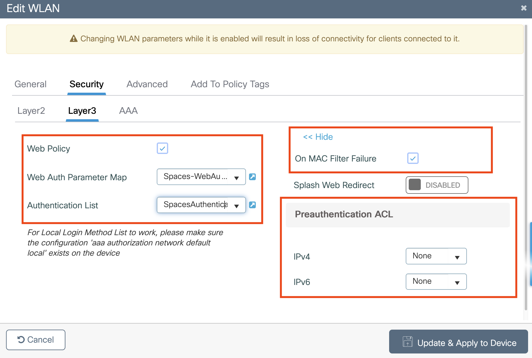
Click the Layer3 tab.
-
Check the Web Policy check box.
-
From the WebAuth Parameter Map drop-down list, choose the Web Auth Parameter Map created previously.
-
From the Authentication List drop-down list, choose the Authentication Server created previously.
-
Check the On Mac Filter Failure check box.
-
If Pre-authentication ACLs were needed and created previously, you can select them here.
-
Click on the Add to Policy Tags tab
-
Link the Policy Tag with the Policy Profile
-
Click Save & Apply to Device.
Apply Policy Tag to AP to Broadcast SSID
-
Navigate to Configuration > Wireless > Access Points
-
Select the AP in question
-
Add the Policy Tag.
-
Click Update & Apply to Device
Important: This causes the AP to restart its CAPWAP tunnel and join back to the 9800 controller.
Captive Portal Configuration (No Authentication)
Once the Wireless Infrastructure has been setup. Configuring the Captivate Portal requires the following tasks:
-
Create or Import Portal
-
Set authentication and data capture settings
-
Configure rules and triggers
For a video guided demo, please see the links below:
How to Configure Captive Portal Rules
Create a Portal
-
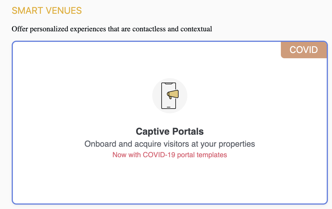
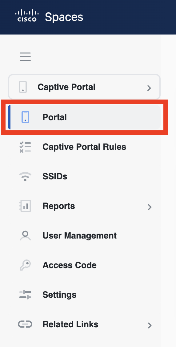
In Cisco Spaces, navigate to Captive Portal App -> Portal
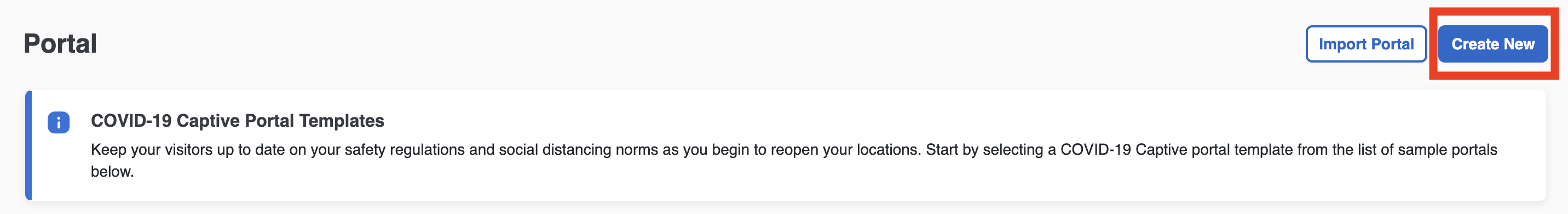
-
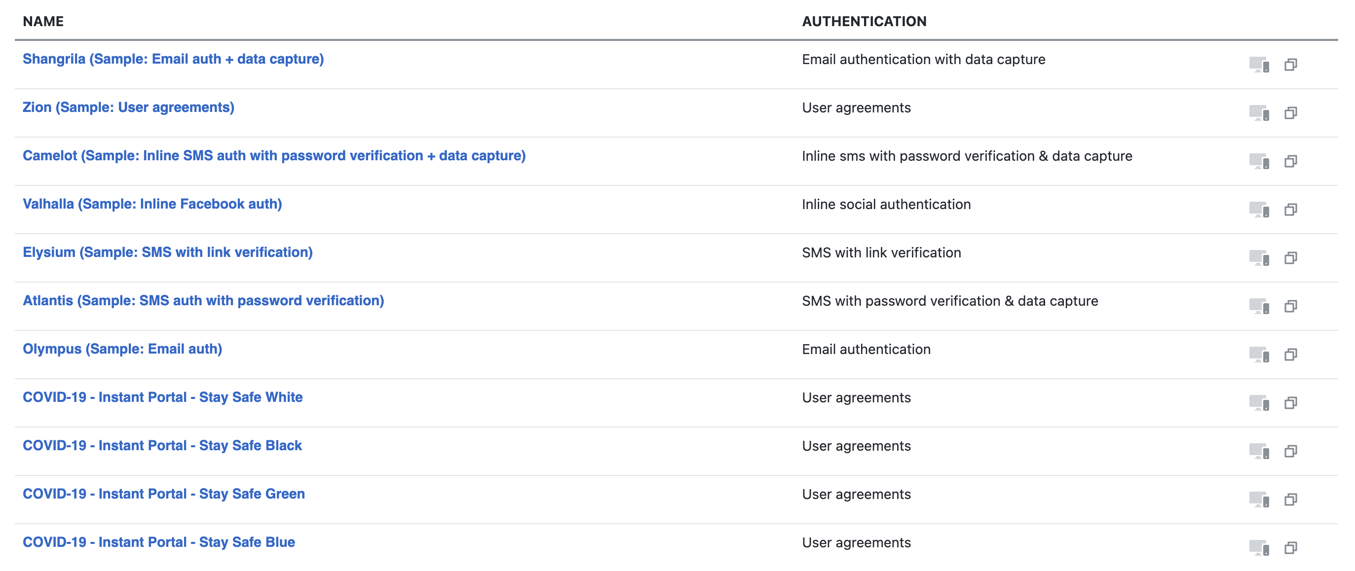
Either create a new portal or use one of the templates like Covid-19 specific templates. If using a templates, select a template and duplicate it for editing.
-
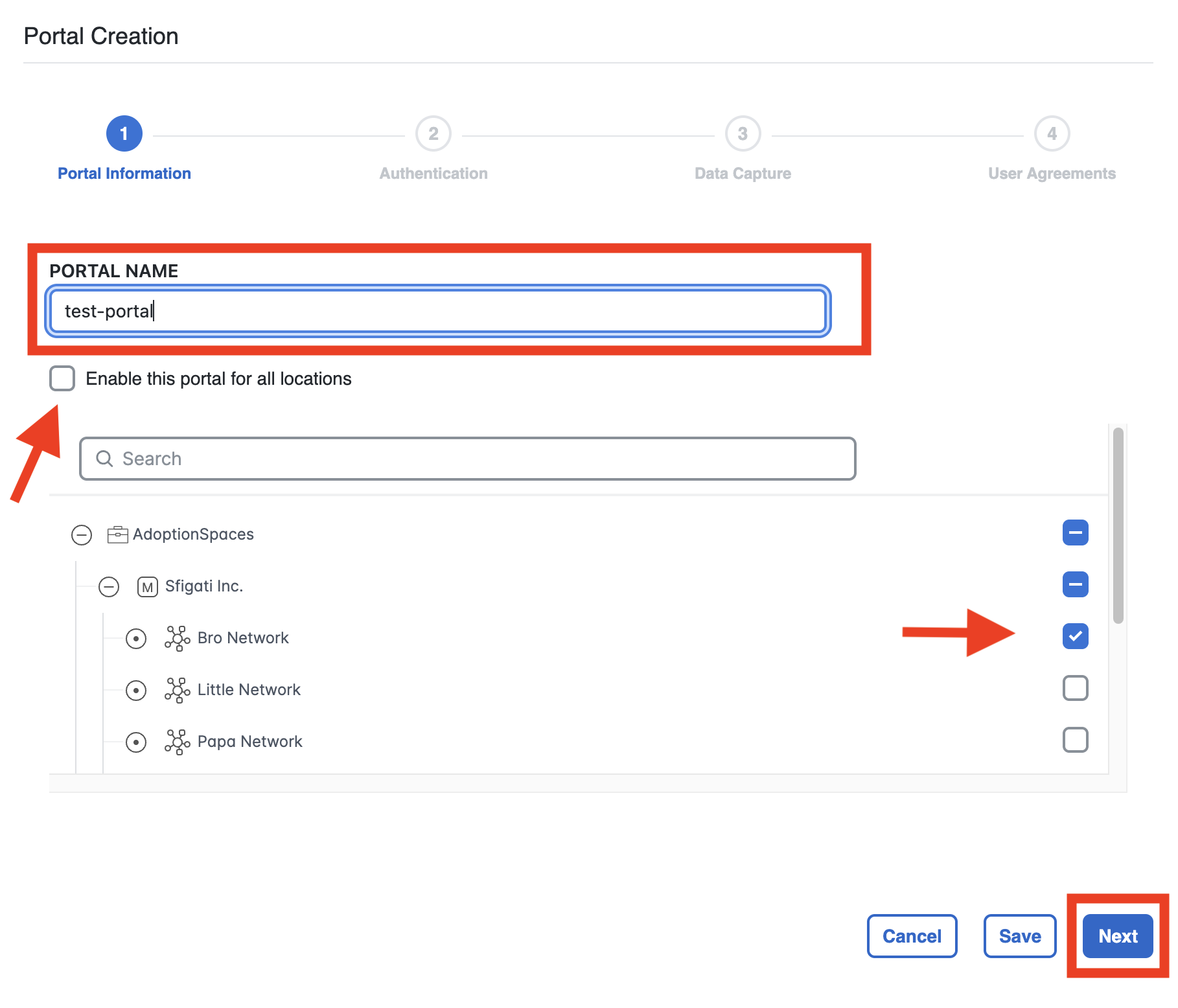
Enter a name for the portal and select the locations where this portal will be used. Select Next
-
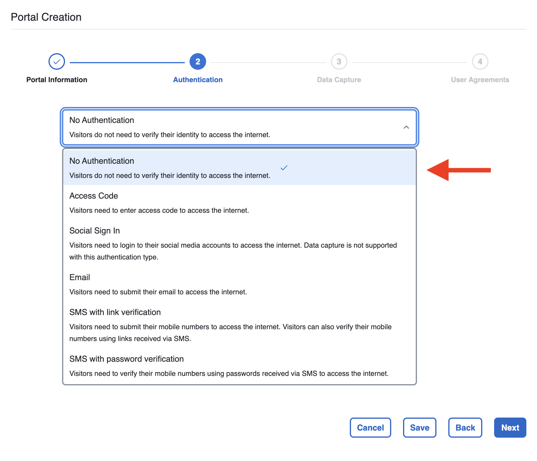
Select the authentication type as per need. For no specific authentications need, select No Authentication as an example.
For other Captive Portal Authentication methods, please refer to our Knowledge Article: [Coming Soon]
-
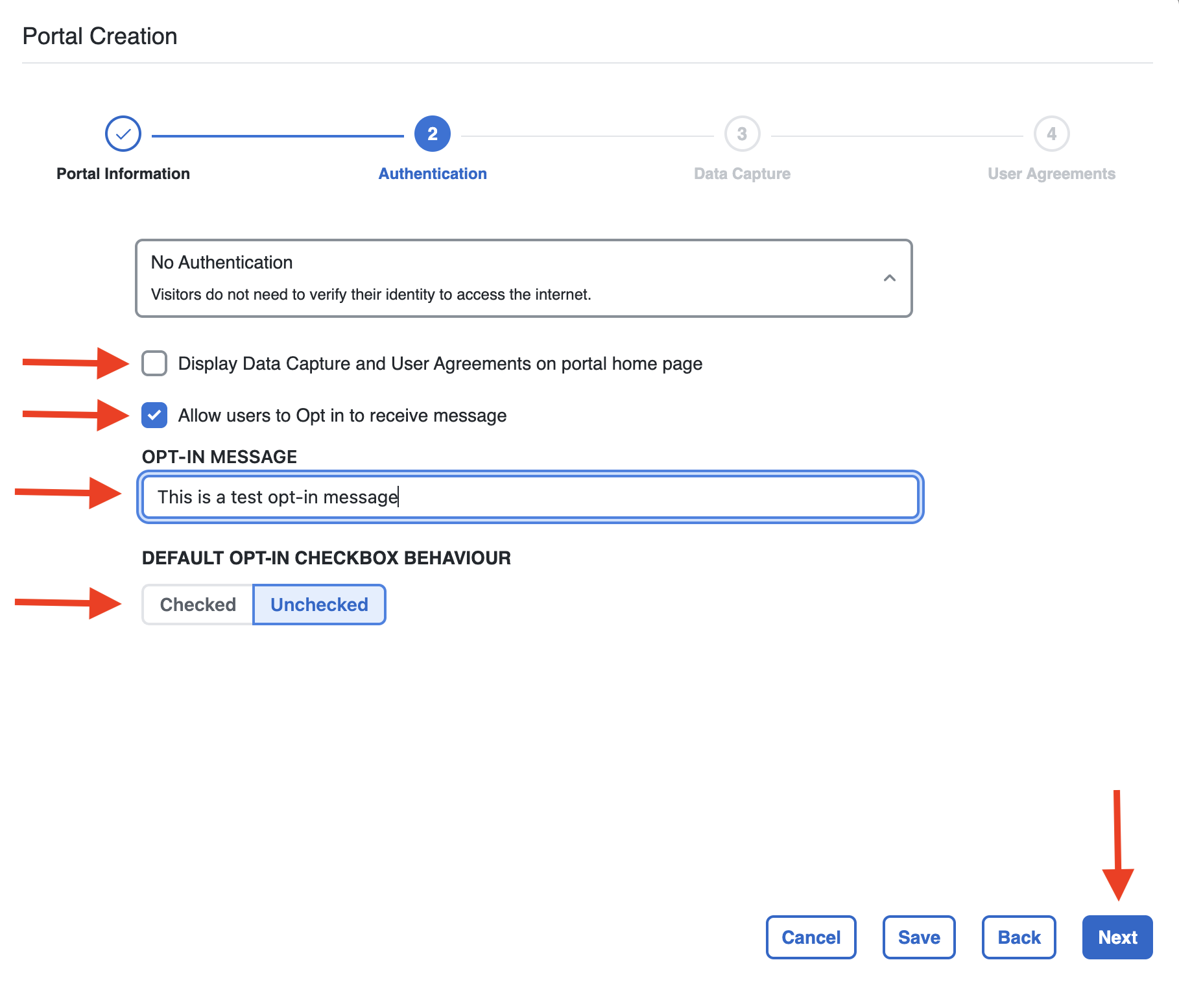
Choose if Data Capture and User Agreements need to be displayed on the portal. Remain unselected if not needed.
-
Choose if users need to specifically agree to opt-in the network. Put the opt-in message, choose the default behaviour.
-
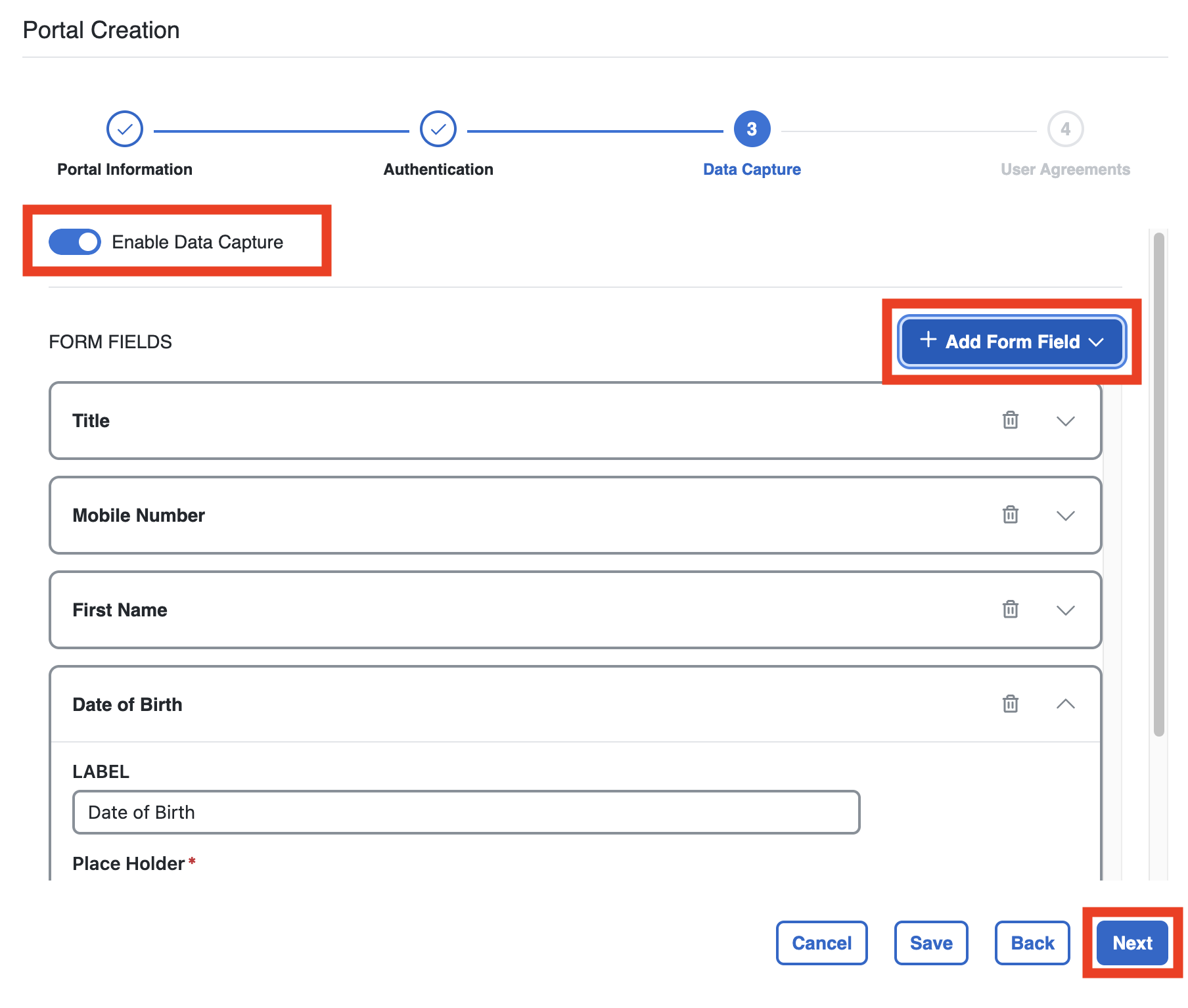
If you want to show a specific Data Capture form that users must complete, enable Data Capture.
-
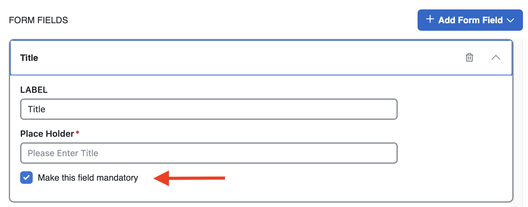
Multiple Fields are available to be chosen, and fields can be made mandatory to be completed by visitors.
-
After all needed fields are chosen, click Next.
-
Select and configure the Terms and Conditions as necessary. Choose whether to Enable Terms and Conditions, Enable Privacy Policy or Age Gating.
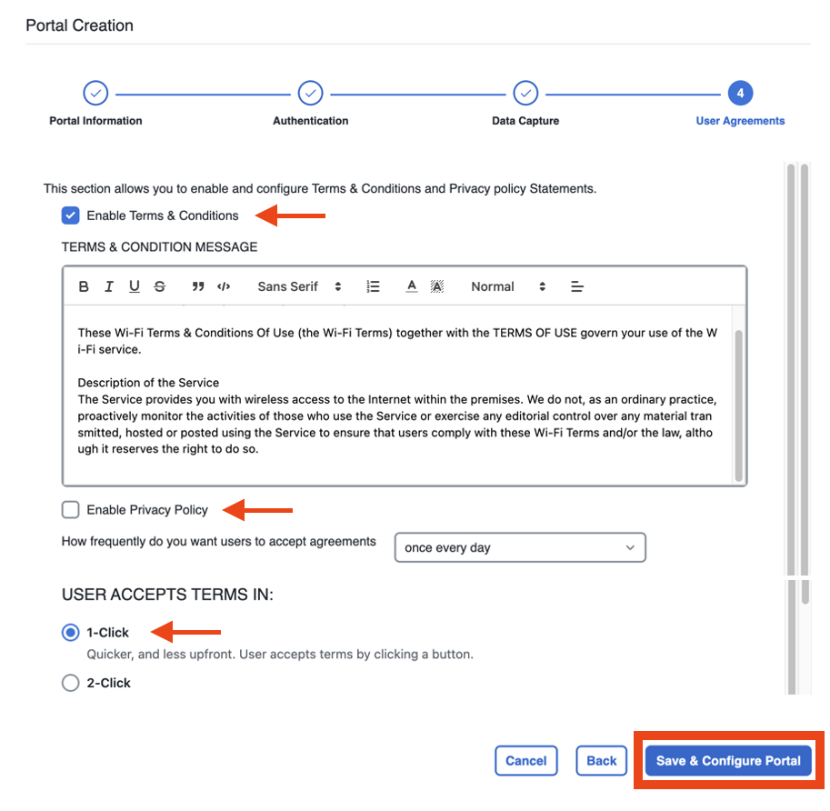
-
Select Save and Configure Portal when done.
Edit the Captive Portal Settings
-
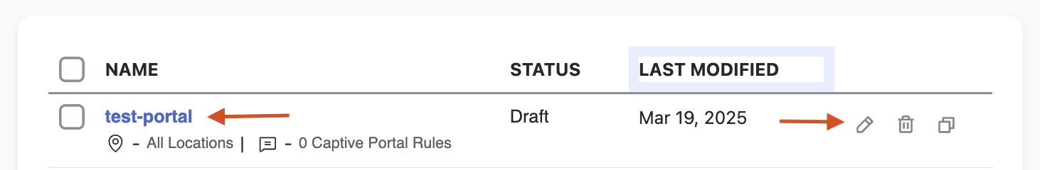
Click the newly created portal to start editing it.
-
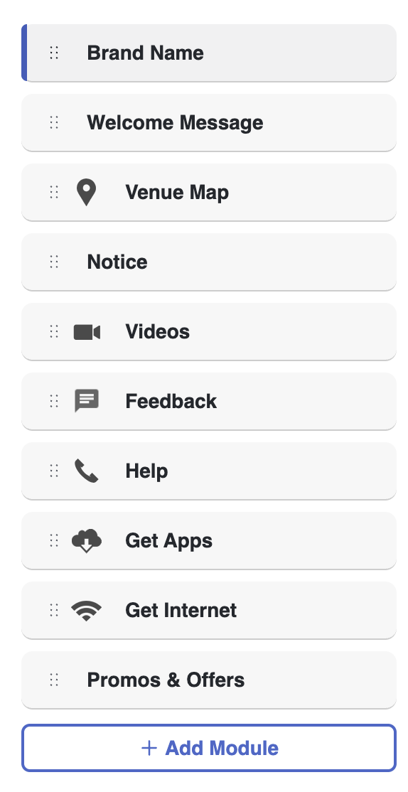
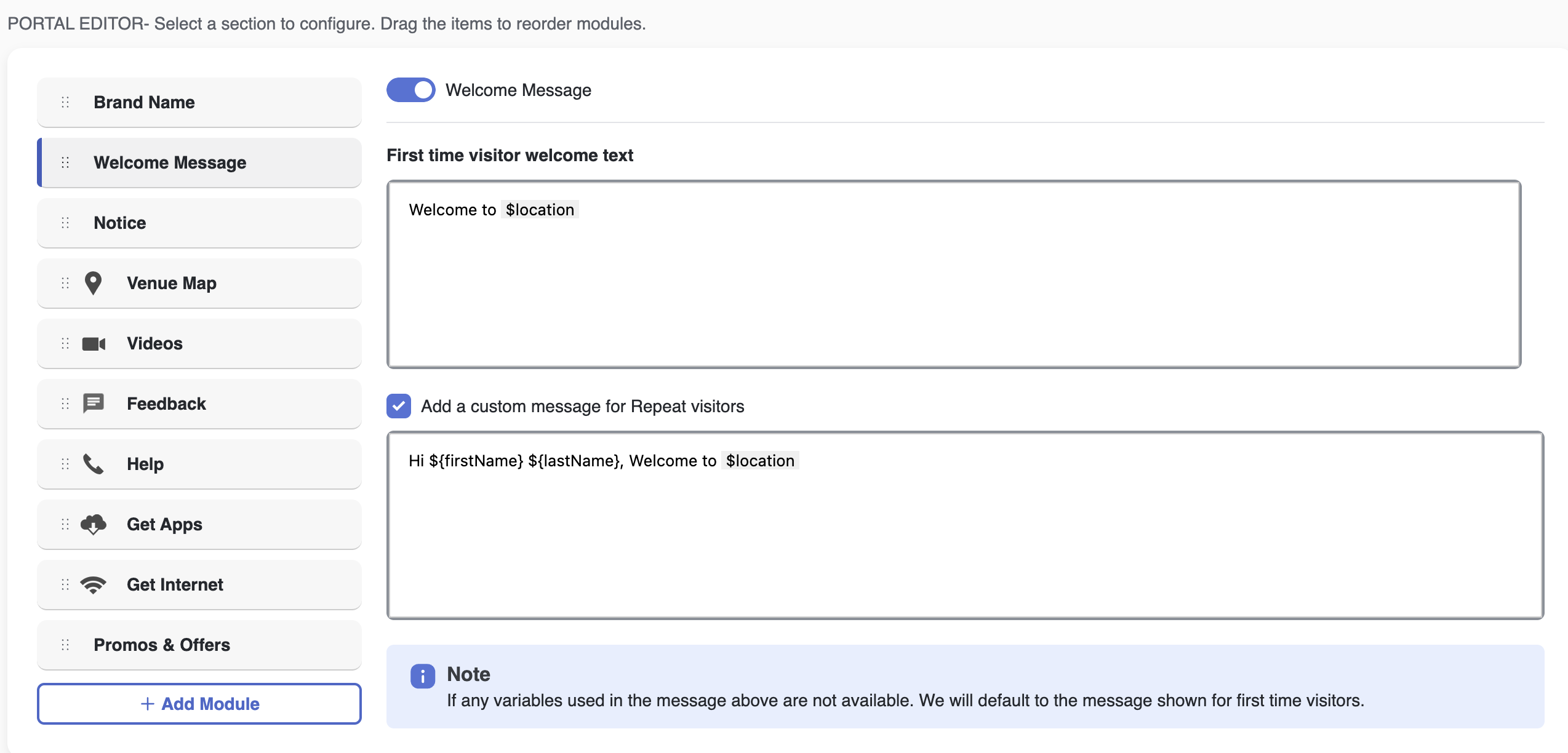
In the Portal Editor window, edit as well as reorder all the modules on the side panel by dragging and dropping them in the desired sequence.
-
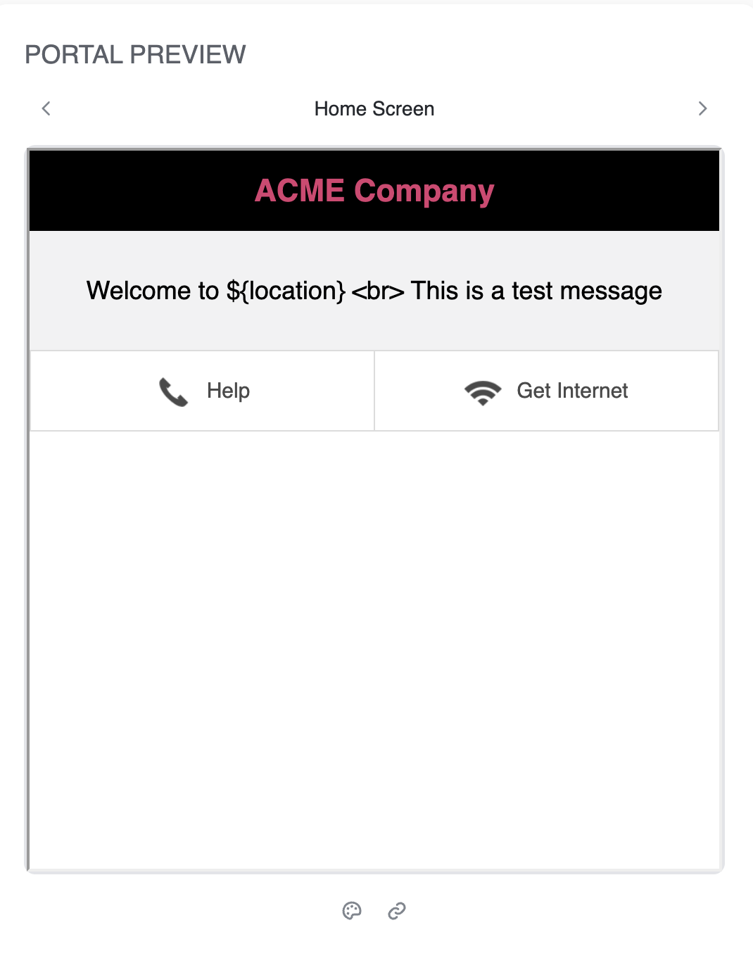
Type in any required welcome message. You can preview the look and feel of the Captive Portal page on the right-side Portal Preview panel that renders draft-changes live.
-
Smart variables can also be added in the messages using $<key>.
|
Smart Variable |
Description |
|---|---|
|
$location |
Location Name as per Hierarchy |
|
$Address |
Address of the location |
|
$State |
State of the location |
|
$Zipcode |
Zip Code of the location |
|
$Country |
County of the location |
|
$City |
City of the location |
-
These variables in this Portal Editor section pertains to the properties of the location where the client is connecting - i.e. which buildings, floor etc.
-
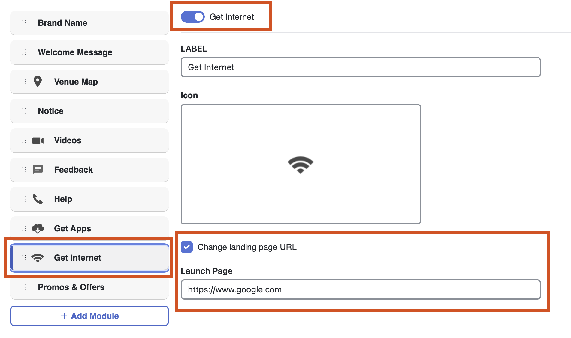
The Landing page upon success can be edited by clicking Get Internet
-
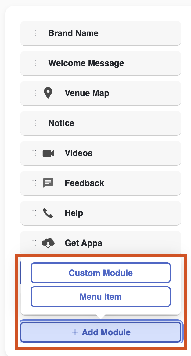
New modules can be added directly with additional content.
-
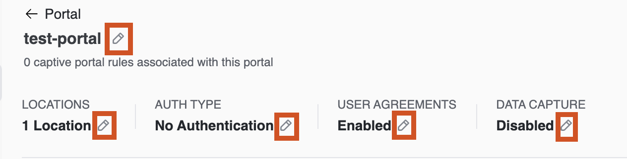
Any previous configurations can be edited by clicking the pencil icon on top of the Portal Editor page.
Create Portal Rules
-
Navigate to Cisco Spaces and then, Captive Portal App -> Captive Portal Rules
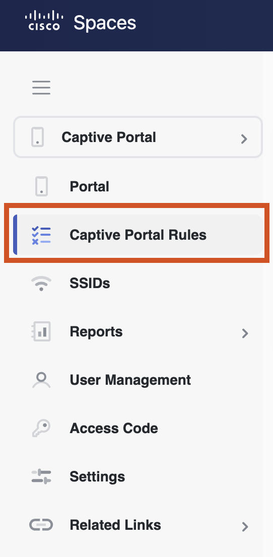
-
Create a new rule to make a specific rule to be triggered as needed by click Create New Rule.
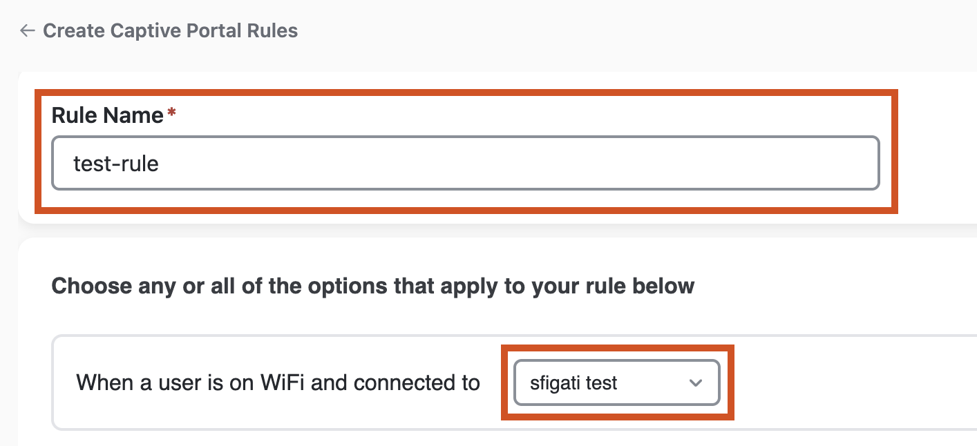
-
Enter a name for the rule. Select which SSID is this rule going to triggered against. The SSID should have already been imported / configured from earlier steps.
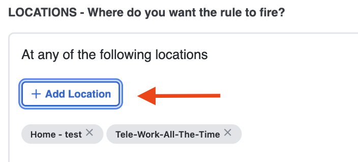
-
Add a location against which this rule should be be triggered. At least one location level needs to be selected.
-
Location needs to be chosen from existing location hierarchy and can be chosen all the way from entire campus levels all the way down to a single zone on a floor.
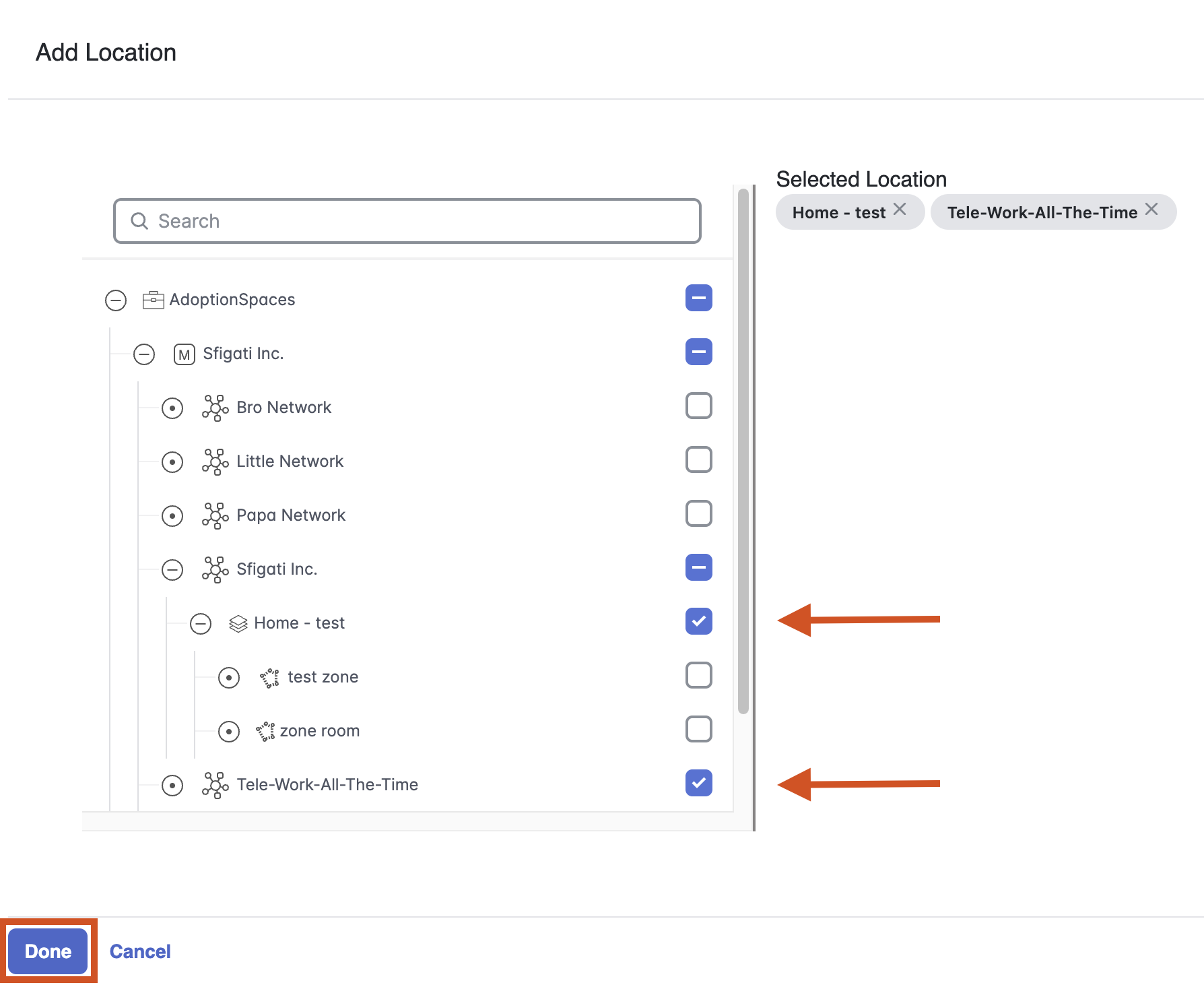
-
Any mix of locations can be selected inc. AireOS, Catalyst or Meraki networks. Click Done once the networks are selected.
The rule will be triggered only if a client is connecting on an AP that exists in the selected location.
-
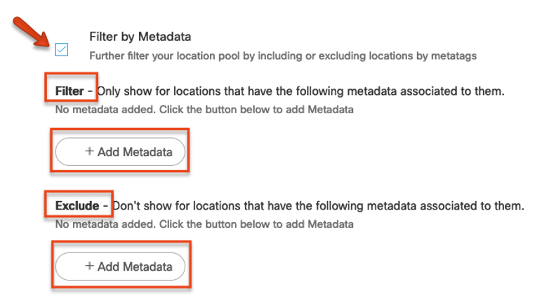
In the Locations Section, if the location hierarchy has metadata tags in use, the rule can also be triggered against very specific locations. Example Use Case: Exclude “yet to open” sites and include “recently opened” sites for a new portal campaign.
-
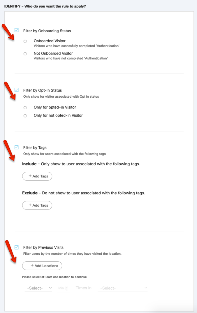
In the Identify section, multiple selections are available to be tweaked. Cisco Spaces saves mac-address used by clients to achieve these filters. The table below details the options:
|
Identify Filter |
Function |
|---|---|
|
Filter by Onboarding Status |
Allows to chose a particular action or portal for visitors who have already completed captive portal authentications previously or not. |
|
Filter by Opt-In Status |
Allows to chose a particular action or portal for visitors who have specifically chosen to opt-in. |
|
Filter by Tags |
Captive Portals application and Location Personas application can tag visitors with specific tags based on their on-location behavior. This tags can be used to trigger a specific action or portal for specific visitors. |
|
Filter by Previous Visits |
Allows to chose a particular action or portal based on whether a client has come into a specific location at least a specific number or between a number of times in particular days or day ranges |
-
In the Actions Section – multiple selections are available. The table below details the options:
|
Actions |
Function |
|---|---|
|
Show Captive Portal |
A specific portal that is created can be chosen to be shown. Different rules can be created to show different types of portals |
|
Seamlessly Provision Internet |
This option can be used to avoid showing the portal and directly onboard visitors’ devices.
|
|
Deny Internet |
This option can be used to reject the device association. |
-
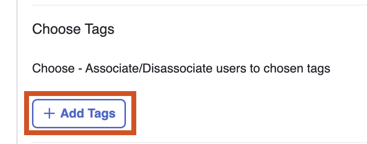
Furthermore, a tag can be created to be assigned to visitors that match all the rules and get successfully onboarded to the network.
-
External APIs can be triggered when a new client is onboarded for the very first time. For triggering an API every time a client is successfully onboarded, ‘Enable for repeat visitors’ can be selected.
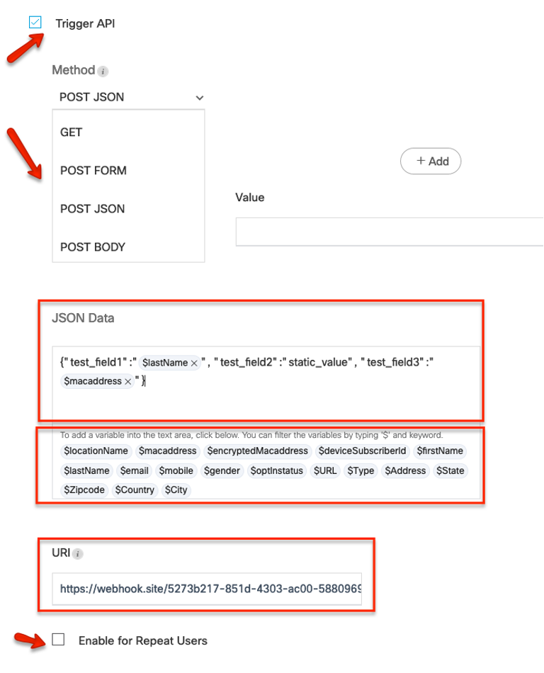
These variables in this API section pertains to the properties of the visitor that is connecting. (Example: visitor name, gender etc.)
Many variables like email, name, address etc. are only available if they were captured for the same visitor using the Data Capture form in the portal.
The following Smart Variables are available in Captive Portals API:
|
Variable Details |
Smart Variables |
|---|---|
|
Location Name |
$locationName |
|
|
|
|
Address |
$Address |
|
Mac-address |
$macaddress |
|
Mobile |
$mobile |
|
State |
$State |
|
Encrypted Mac-address |
$encryptedMacaddress |
|
Gender |
$gender |
|
Zip Code |
$Zipcode |
|
Device subscriber ID |
$deviceSubscruberId |
|
Opt in Status |
$optinstatus |
|
Country |
$Country |
|
First Name |
$firstName |
|
URL |
$URL |
|
City |
$City |
|
Last Name |
$lastName |
|
Type |
$Type |
-
View the overall created rule in the summary section on the right-side of the dashboard.
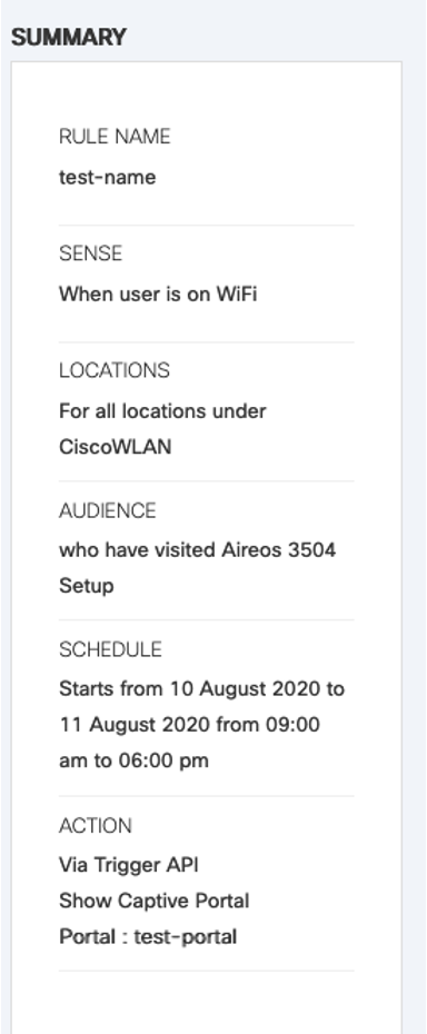
-
If satisfied with the rule, click Save & Publish.
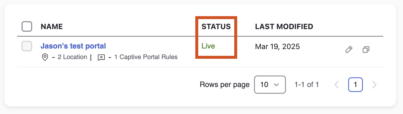
-
Once the rule is pushed, the Captive Portal will show up as being Live in the Portal window.
FAQ
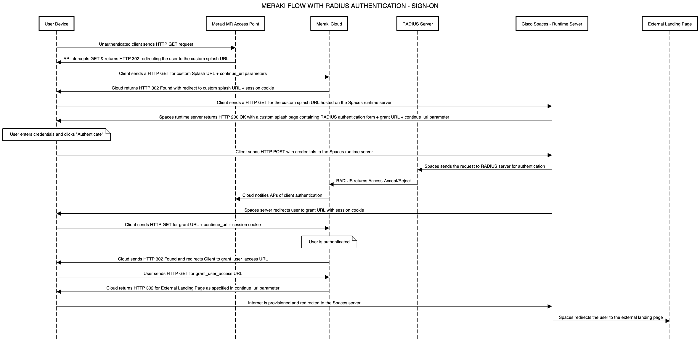
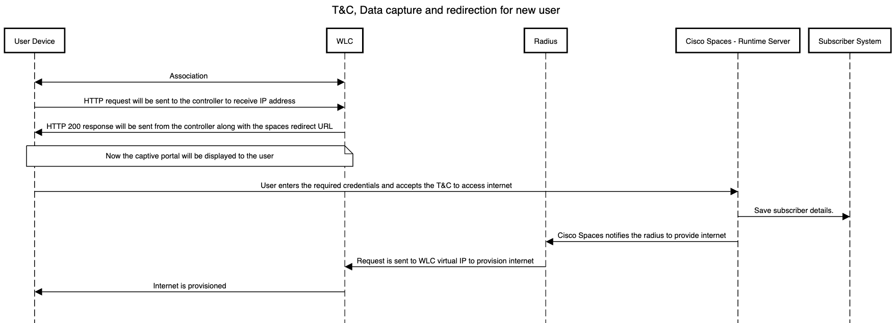
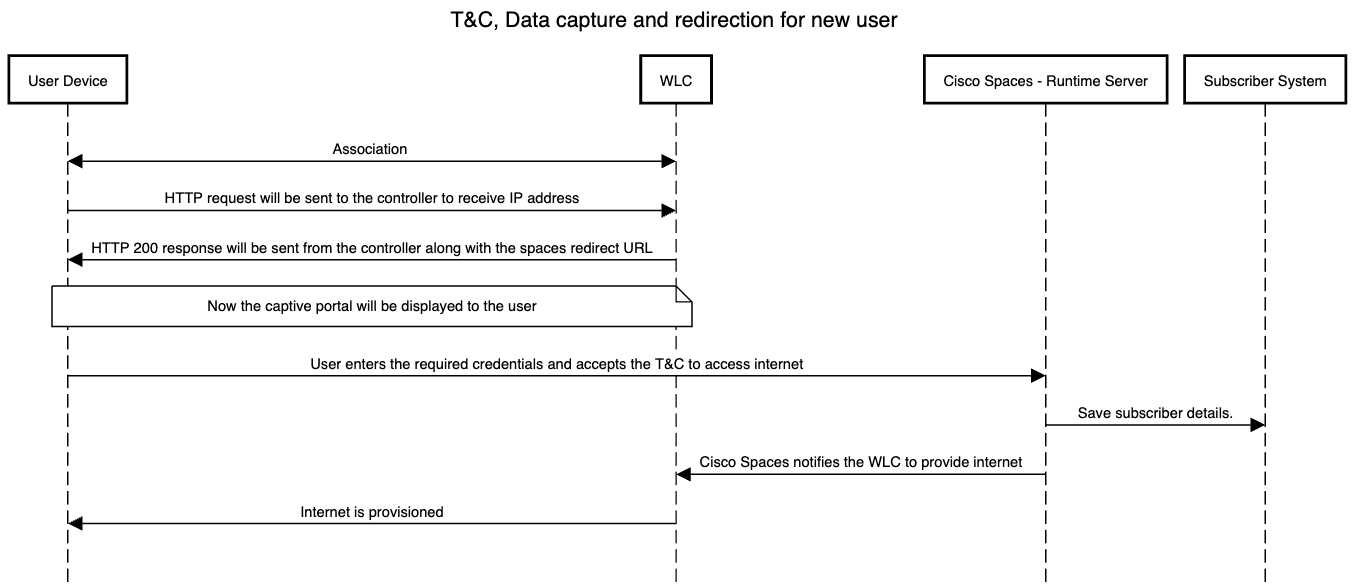
What does the complete data flow look like from guest end-device to having Captive Portal provision Internet?
Meraki Data Flow (with Radius)
Meraki Data Flow (without Radius)
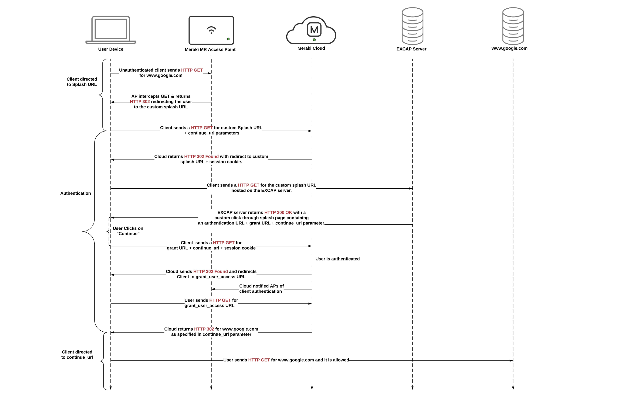
Catalyst Data Flow (with Radius)
Catalyst Data Flow (without Radius)
What if my certificate authority won’t issue a certificate for the Catalyst 9800’s virtual IP (192.0.2.1)?
When configuring a Captive Portal on a Catalyst 9800 Wireless Controller, it’s essential to install a trusted SSL/TLS certificate that matches the controller’s virtual interface IP address or DNS name. Without a trusted certificate, users will encounter browser security warnings when redirected to the captive portal.
The virtual IP address used by the Catalyst 9800 is typically 192.0.2.1, which is a reserved, non-routable address used internally by the controller.
However, many public Certificate Authorities (CAs) will not issue certificates that include private or reserved IP addresses (such as 192.0.2.1) in the Subject Alternative Name (SAN) field, as this violates industry standards and CA policies.
Workaround:
To resolve this, use a domain name instead of the IP address in the certificate’s SAN field.
Example 1:
-
WLC virtual IP:
192.0.2.1 -
Chosen domain:
wlc-portal.company.com -
Internal DNS record:
wlc-portal.company.com → 192.0.2.1 -
Certificate SAN:
DNS:wlc-portal.company.com(no IP addresses)
Example 2:
-
WLC virtual IP:
192.0.2.1 -
Chosen domain:
guestwifi.melbournebranch.local -
Internal DNS record:
guestwifi.melbournebranch.local → 192.0.2.1 -
Certificate SAN:
guestwifi.melbournebranch.local(no IP addresses)
Follow these steps:
-
Choose a Domain Name: Select a unique domain name (e.g.,
wlc-portal.example.com) to represent the WLC’s virtual interface. -
Configure the WLC: In the Catalyst 9800 configuration, set the virtual interface’s DNS name to the chosen domain name.
-
Log in to the Catalyst 9800 WLC web GUI
-
Navigate to Configuration > Security > Web Auth
-
Click the “global” Web Auth to begin configuration
-
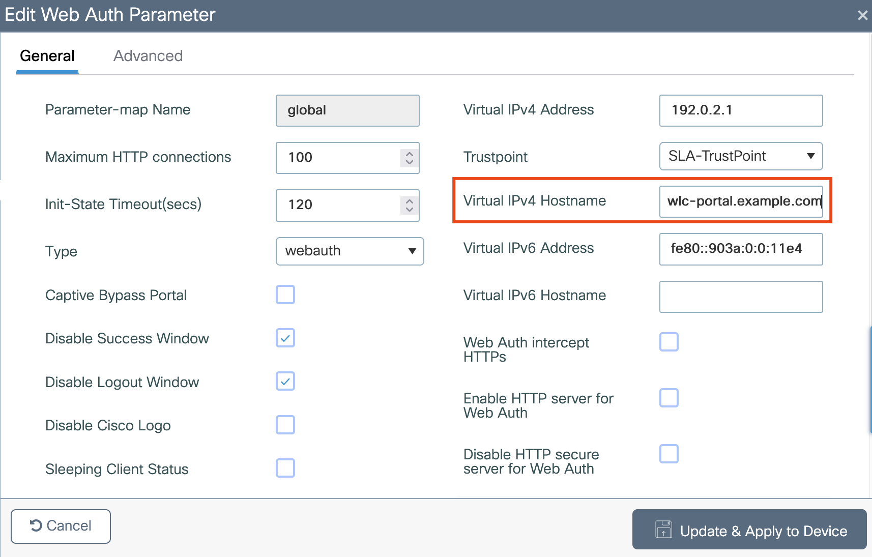
Locate Virtual IPv4 Hostname
-
Enter your chosen domain name (e.g.,
wlc-portal.example.com) -
Click Update & Apply to Device
-
Alternatively, via CLI:
|
CLI Config |
|---|
|
config
|
-
Update Internal DNS: On your internal (on-premises) DNS server, create a DNS record that resolves the domain name to the virtual IP address (
192.0.2.1). -
Obtain the Certificate: Request a certificate from a public CA with the chosen domain name in the SAN field—do not include the private IP address.
-
Install the Certificate: Upload and apply the certificate to the Catalyst 9800 controller.
This approach ensures clients see a trusted certificate when accessing the captive portal, while avoiding issues with CAs rejecting certificates that reference private IPs.
-
This workaround relies on all client devices using your internal DNS when connecting to the wireless network.
-
If devices use external DNS (e.g., 8.8.8.8), they may not be able to resolve the domain, potentially causing captive portal issues.
-
Always ensure the domain name used is not publicly resolvable to avoid conflicts or security concerns.
-
After changing the virtual IP DNS name, you may need to clear client browser DNS caches or disconnect/reconnect Wi-Fi clients for changes to take effect.